Principal Inspection of 50 Highway Structures – Wakefield
Project Summary
Client: Wakefield Council (Highways Structures)
Location: Wakefield District, West Yorkshire, United Kingdom
Contract: RFS23-45 – Principal Inspections of 50 Bridges (NEC4 Professional Services Contract)
Project Type: Principal Inspections of 50 highway bridges, culverts and underpasses in accordance with DMRB CS 450
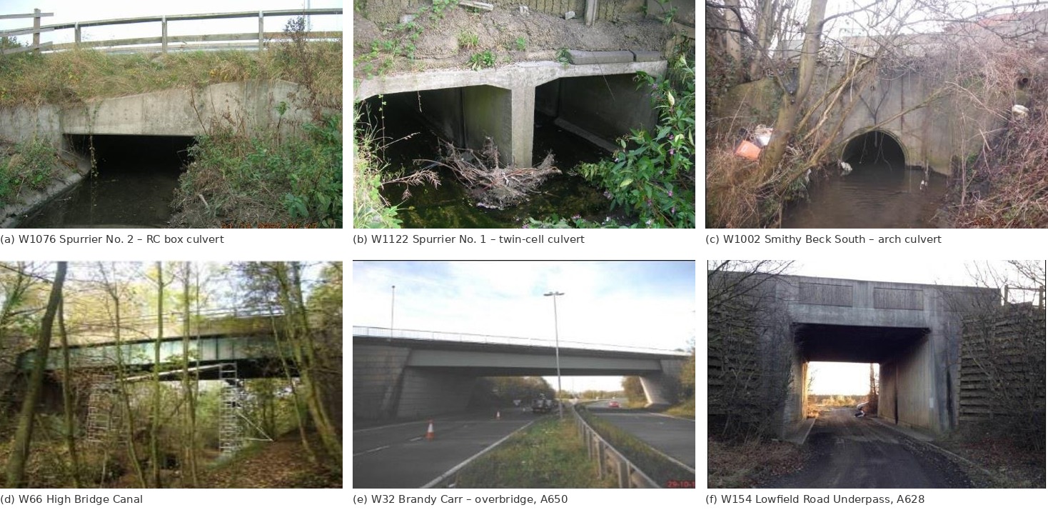
Structure Types: Masonry arches, reinforced concrete, steel and corrugated metal structures, mostly over watercourses
Project Status: Ongoing – site inspections and reporting in progress
Services Provided
-
Principal Inspections of 50 highway structures to DMRB CS 450
-
Desk study and review of previous inspection records
-
Programme of Works and Gantt chart for client approval
-
Phase-specific and structure-specific RAMS and site sheets
-
Confined space entry, non-entry CCTV and water-based inspections
-
Access planning, including MEWP, scaffold, underbridge unit and Chapter 8 traffic management
-
Bridge Condition Indicator (BCI) scoring and PI reporting to the client's template
1. Project Overview
Beta Design Consultants (BDC) was appointed by Wakefield Council under contract RFS23-45 to carry out Principal Inspections (PIs) of 50 highway structures across the Wakefield district. The commission is delivered under an NEC4 Professional Services Contract.
The portfolio consists mainly of small- and medium-span structures carrying the local road network over becks and other watercourses. It includes masonry arch bridges, reinforced concrete bridges and box culverts, steel structures and corrugated metal culverts. Many of the structures are low-headroom culverts, so a large part of the work has to be carried out in confined spaces or from the water.
BDC is responsible for the whole inspection service. This covers programming, access, traffic management, confined space equipment and rescue provision, the site inspections, condition scoring and the PI reports issued to the client.
2. Technical Background: Principal Inspections of Highway Structures
Highway structures in the UK are inspected under DMRB CS 450 (Inspection of highway structures) and the associated guidance for local authority bridge stock. Regular inspection gives the asset owner the condition information needed to keep structures safe, to plan maintenance and to prioritise funding.
Different inspection types give different levels of information:
|
Inspection type |
Typical frequency |
Purpose |
|
Safety Inspection |
Routine, with highway patrols |
Identify obvious defects that present an immediate hazard to users |
|
General Inspection (GI) |
Every 2 years |
Visual inspection of all parts visible from ground level or a safe position |
|
Principal Inspection (PI) |
Normally every 6 years |
Close examination, within touching distance, of all inspectable parts of the structure |
|
Special Inspection |
As required |
Targeted investigation following an event, a defect of concern or a change in loading |
A Principal Inspection is the most detailed of the routine inspections. Each element of the structure is examined within touching distance, which for many of the Wakefield culverts means entering the barrel, working in the watercourse or bringing in specialist access equipment.
The findings are recorded using the Bridge Condition Indicator (BCI) system. Each element is given a severity rating (1 to 5) and an extent rating (A to E), together with a defect type code. These ratings are combined with the importance of each element to give an average and a critical condition score for the structure. Across a whole bridge stock, these scores allow the asset owner to compare structures and target maintenance where it is most needed.
3. The Structure Portfolio and Typical Defects
Most of the 50 structures cross becks and small watercourses, and many are culverts with limited headroom. The materials and forms of construction vary across the portfolio, and each has its own deterioration mechanisms that the inspection team must look for:
|
Structure type |
Typical defects |
Deterioration mechanism |
|
Masonry arches |
Mortar loss, ring separation, longitudinal and diagonal cracking, spalled units, spandrel wall movement |
Water ingress, frost action, vegetation, settlement or spreading of abutments |
|
Reinforced concrete |
Cracking, spalling, exposed and corroded reinforcement, leaching and efflorescence |
Carbonation and chloride-induced corrosion, failed waterproofing and joints |
|
Steel |
Coating breakdown, corrosion and section loss, especially at bearings and connections |
Moisture, de-icing salts, debris traps and poor drainage |
|
Corrugated metal culverts |
Invert corrosion and section loss, deformation of the barrel, scour at the ends |
Abrasive and wet flow at the invert, loss of surrounding fill, changes in shape under load |
|
All structures over water |
Scour at foundations and headwalls, undermining, debris build-up, blocked trash screens |
Flood flows and changes in the river bed |
4. Planning and Programming
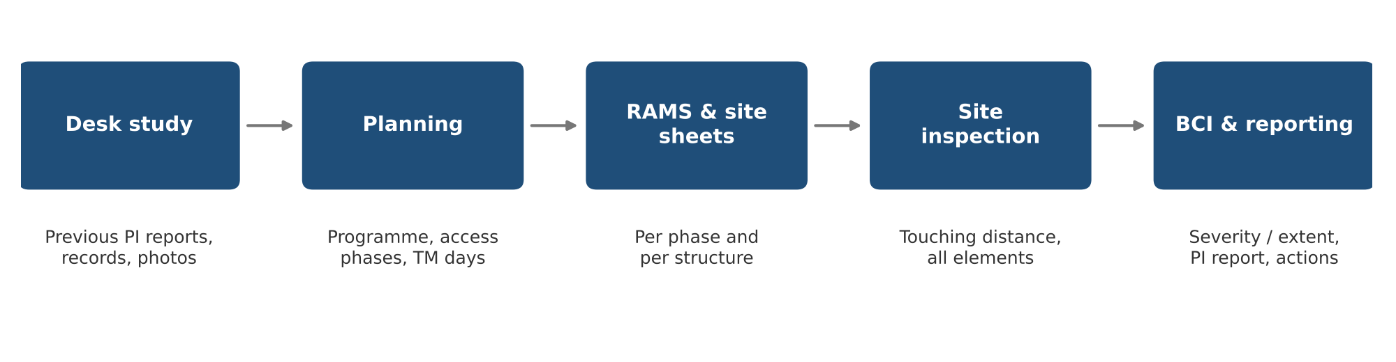
With 50 structures spread across the district, careful planning was key to delivering the inspections safely and on programme. BDC began with a desk study of the existing records and the photographs from previous PIs. This was used to establish the form, size, headroom and likely access method of each structure before any site work started.
Grouping by access method
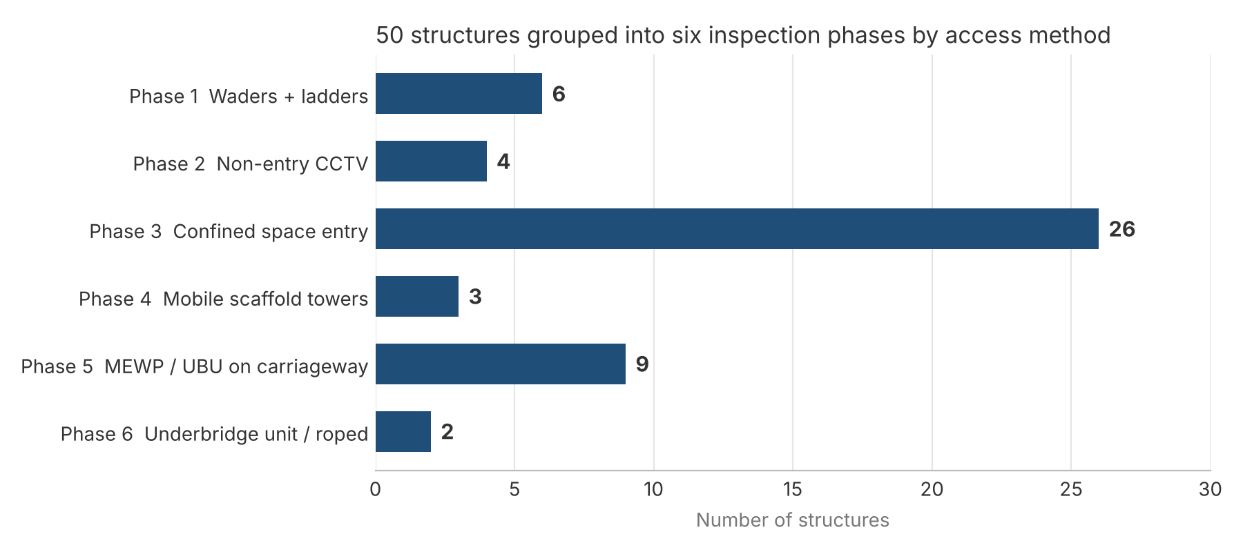
Rather than inspecting the structures in geographical order, BDC grouped them into six phases according to the access method each one needs. Each team, and each set of equipment, is then mobilised once per phase rather than once per structure. This shortens the programme, reduces cost and keeps the same specialist equipment and trained operatives working together.
|
Phase |
Access method |
Structures |
Typical use |
|
1 |
Waders and ladders |
6 |
Shallow watercourses with sufficient headroom |
|
2 |
Non-entry CCTV |
4 |
Barrels too small or low for safe entry |
|
3 |
Confined space entry |
26 |
Culverts and barrels requiring entry by a trained team |
|
4 |
Mobile scaffold towers |
3 |
Bridges over a canal and over land with soffits out of reach from the ground |
|
5 |
MEWP / underbridge unit on the carriageway |
9 |
Overbridges, footbridges and underpasses on A roads, under traffic management |
|
6 |
Underbridge unit and roped access |
2 |
Structures with no safe access from below |
BDC prepared the Programme of Works and Gantt chart for the client's approval, together with an individual site sheet for every structure. Each site sheet records the location and coordinates, access route and parking, the type of watercourse, expected water depth and headroom, site-specific hazards and the nearest A&E hospital. Inspectors arrive at each site already aware of its particular risks.
Traffic management
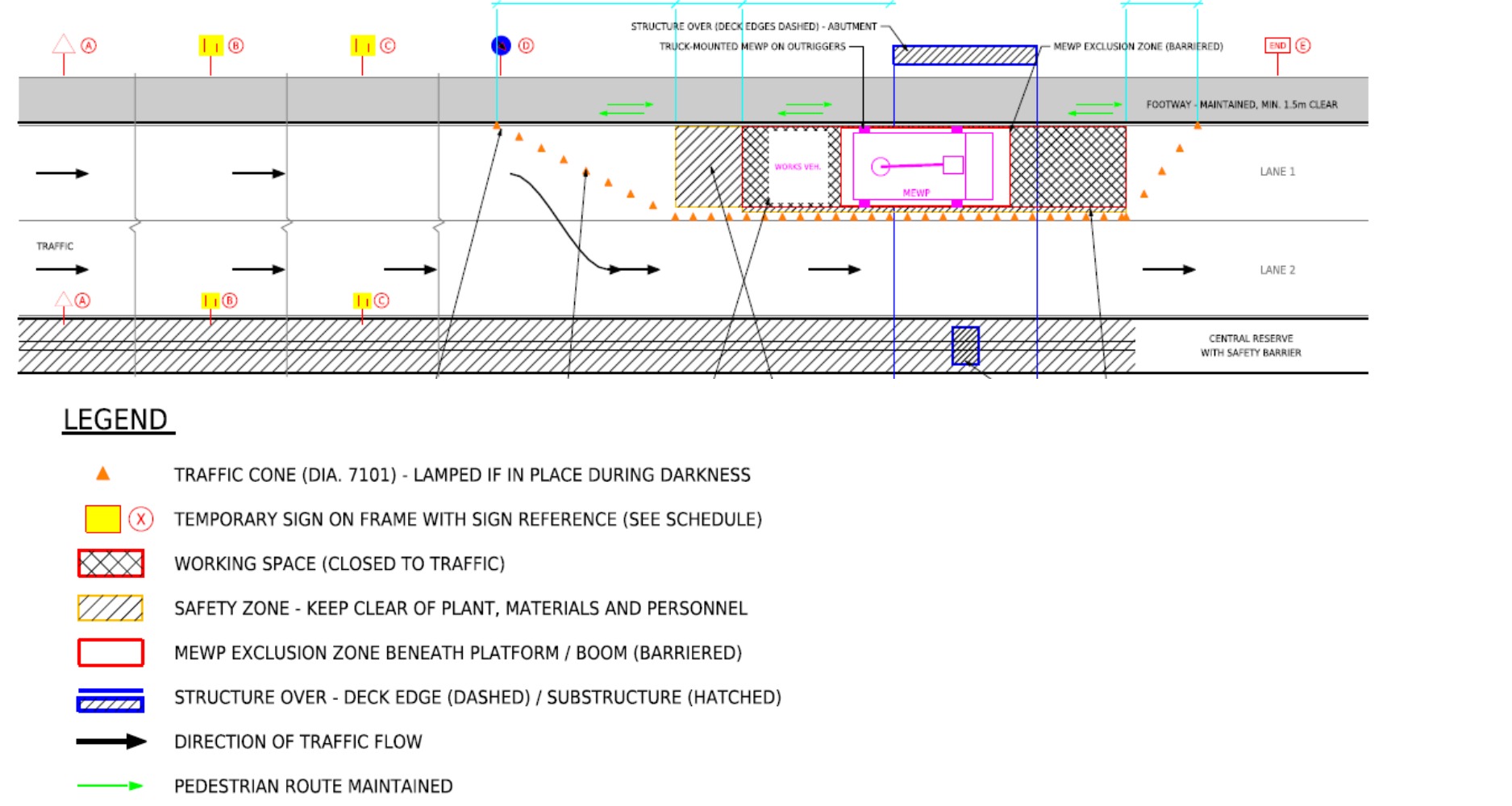
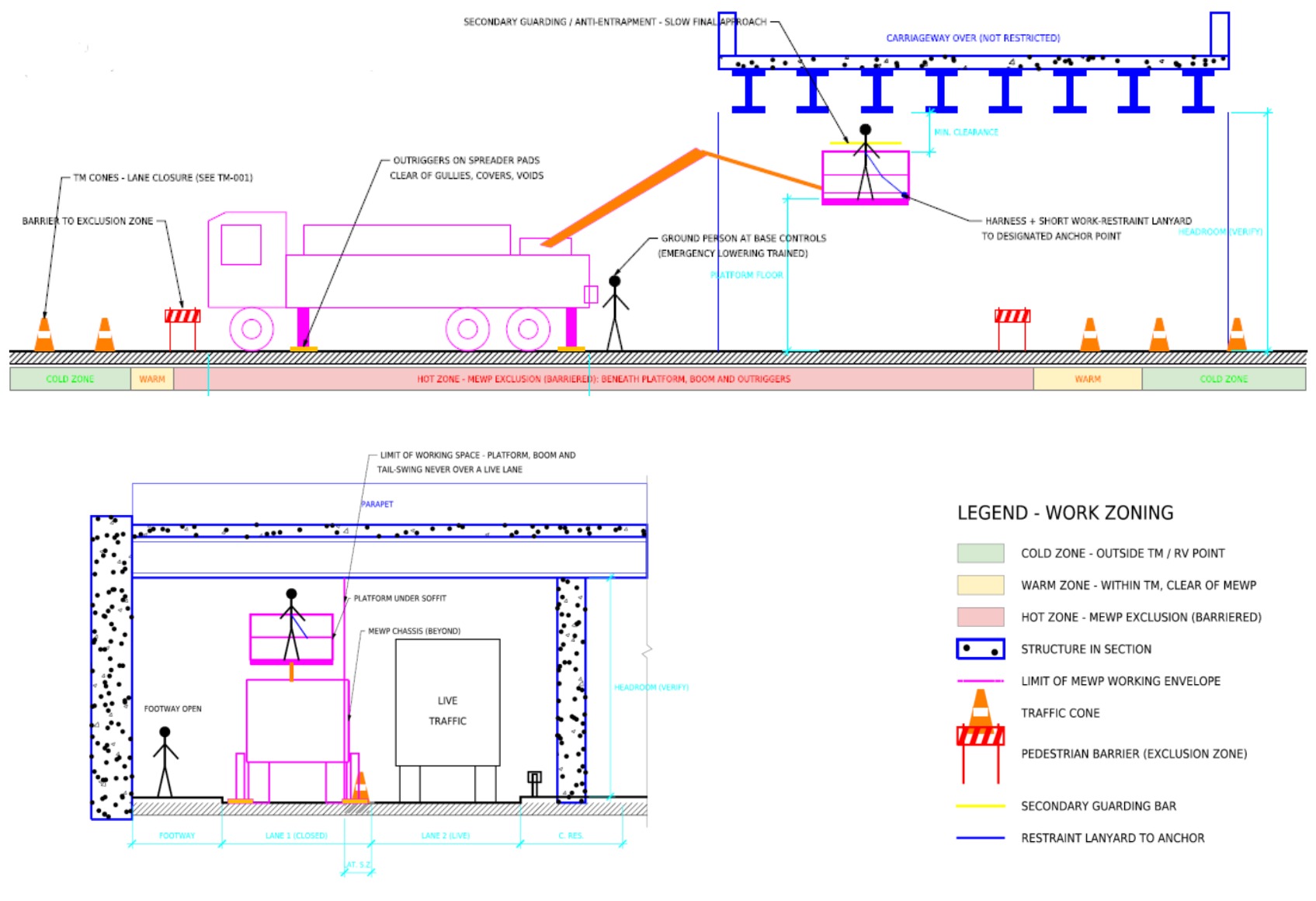
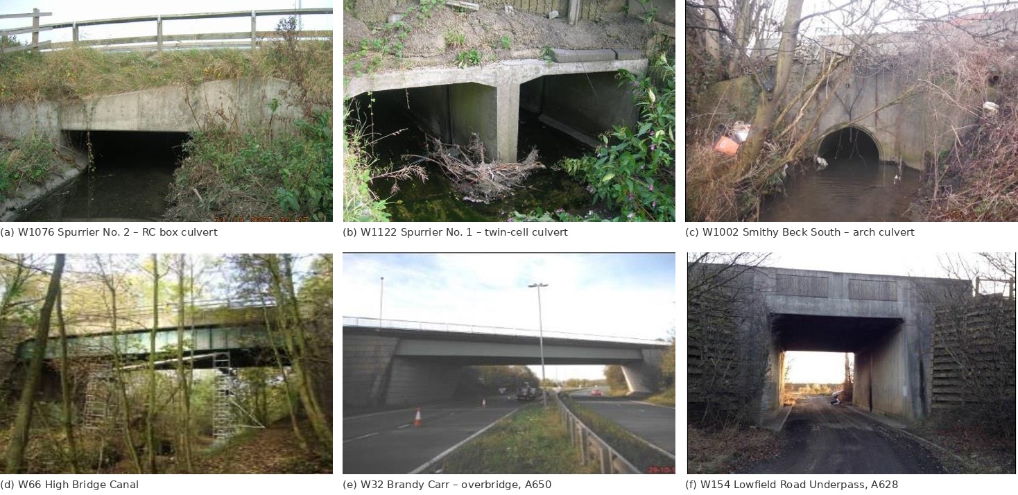
The nine Phase 5 structures are overbridges, footbridges and underpasses on the A6194, A650, A638, A655 and A628, ranging from the 61 m single-span W168 Power Station bridge over the River Calder to short reinforced concrete underpasses beneath the A628. Their soffits, beams and bearings can only be reached from a MEWP set up on the carriageway, so every one of them needs temporary traffic management to Chapter 8 of the Traffic Signs Manual.
BDC prepared typical traffic management and MEWP set-up drawings for the RAMS, and agreed the requirements for each structure against the restrictions set by Wakefield Council:
-
Restricted working windows: lane closures beneath the A650 and A638 bridges are only permitted between 09:30 and 15:30, so each of these inspections is planned as a single-day closure within that window.
-
Shuttle working: at W168 the A6194 is reduced to a 3.5 m running lane under vehicle-operated signals while an underbridge unit works from the deck, keeping the combined cycleway and footway open.
-
Footbridges and bridleways kept open: the footbridges at W2002 (Outwood School) and W2001 stay open throughout, with work beneath the school footbridge timed to avoid arrival and dismissal. The bridleways beneath the A628 underpasses (W154 and W152) remain open under guidance from site staff.
-
No platform over a live lane: where the soffit cannot be reached from one closed lane, the platform is stowed and the closure switched to the next lane, so the platform is never positioned above live traffic.
-
Permits and lead times: permits and any Temporary Traffic Regulation Orders are obtained from the council in advance, with the longest lead time (12 weeks at W154) built into the programme.
5. Health and Safety
Working in confined spaces, in watercourses and next to live traffic are the main hazards of the commission. BDC prepared Risk Assessments and Method Statements (RAMS) for each inspection phase, supported by a RAMS for each structure, before any work on site began.
-
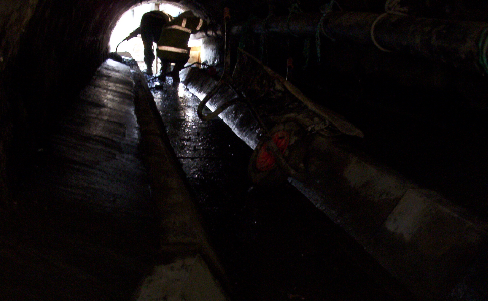
Confined space entry: work is carried out under the Confined Spaces Regulations 1997 by a trained team, with continuous gas monitoring, a top-person at the entrance at all times and a rescue plan in place before entry.
-
Reducing entry: photographs from previous inspections were reviewed to flag structures where the headroom looked too low for safe entry. These were moved to CCTV or end inspection, so that nobody enters a confined space unless the inspection requires it.
-
Working near water: water levels and weather forecasts are checked before each visit, and entry into a watercourse is postponed if flows are too high.
-
Work at height and lifting: scaffold, MEWP and underbridge unit work follows the Work at Height Regulations 2005, LOLER 1998 and PUWER 1998, with IPAF-trained operators.
-
Working on the highway: traffic management is designed and installed to Chapter 8 by an accredited contractor (National Highway Sector Scheme 12A/B or 12D) under a permit from the council. BDC staff do not place or move traffic management equipment.
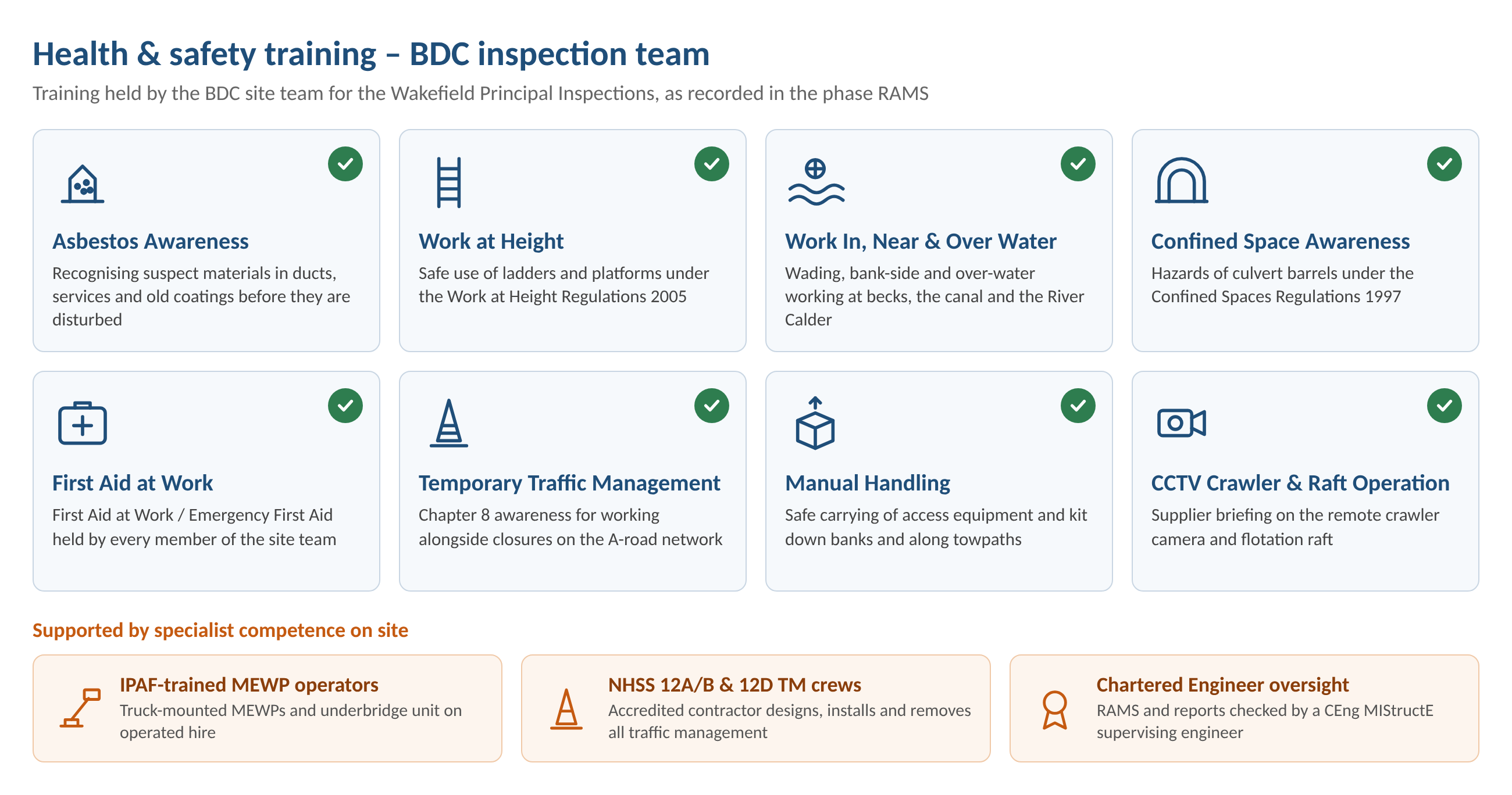
Every member of the BDC site team is trained for the hazards of the commission, and specialist tasks such as MEWP operation and traffic management are carried out by accredited partners. Training records are checked for each phase and recorded in its RAMS before any work on site starts.
6. Site Inspection Methodology
Each structure is inspected within touching distance of all its accessible elements, including the deck or barrel, abutments and wingwalls, headwalls, parapets, bearings where present, the watercourse bed and the embankments. The method adopted depends on the phase:
-
Phase 1 – Waders and ladders: inspectors walk the barrel or the watercourse beneath the structure, using ladders to reach the soffit and headwalls.
-
Phase 2 – Non-entry CCTV: the barrels of four culverts (W1076, W114, W1122 and W1002) are too low, long, multi-celled or obstructed by trash screens to inspect on foot. They are surveyed remotely, with nobody entering the barrel.
-
Phase 3 – Confined space entry: a trained team enters the culvert under a permit, with gas monitoring, communications and a top-person at the entrance.
-
Phase 4 – Mobile scaffold towers: aluminium towers to BS EN 1004-1 are erected beneath the deck by PASMA-trained staff at W66 High Bridge Canal, W50 Newmiller Railway and W6036 Waggon Lane. At W66 the towers stand on the towpath and are never erected over the water.
-
Phases 5 and 6 – MEWP, underbridge unit and roped access: 21 m and 22 m truck-mounted MEWPs and an underbridge unit are supplied on operated hire with IPAF-trained operators. Inspectors on the platform wear a harness with a short work-restraint lanyard.
CCTV and MEWP inspection equipment
BDC selected the inspection and access equipment for each phase according to the form of each structure and how it could be reached.
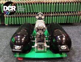
For Phase 2, BDC hired a Proteus Lite crawler system from DCR Inspection Systems, with a control unit and 250 m of power and data cable. The crawler sits on a camera flotation raft with its wheels removed (Figure 9). The raft is let downstream with the flow and held on a rope at each area to be inspected. The camera head is panned and tilted from the control unit on the bank, and the soffit, walls, invert and joints are recorded continuously with chainage. Afterwards the raft is recovered on the rope and cable, or retrieved at the downstream portal.
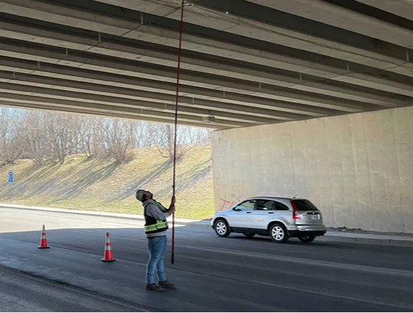
Where an element can be seen but not safely reached, a bridge inspection pole camera (Figure 10) is used. It gives close-up images of soffits, bearings, joints and culvert portals from the bank, the footway or the deck, without setting up access equipment or entering the watercourse.
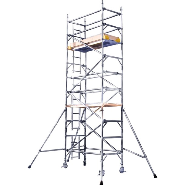
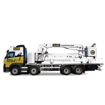
from below, are inspected with a 20.60 m diesel underbridge unit (Figure 11) or work platform (Figure 12). The unit works from the bridge deck inside a traffic management closure and reaches under the deck, so the inspector can examine the beams, bearings and substructure at touching distance.
Findings are recorded on site using a mobile and tablet-based digital field book developed by BDC for this commission. Defects, photographs and severity and extent ratings are captured against each element at the time of inspection. This reduces transcription errors and speeds up the preparation of the reports.
7. Condition Recording and Bridge Condition Indicator
The condition of each element is recorded on the BCI form in the client's PI report template. For each element BDC records:
-
Severity (1 to 5): from no significant defect (1) to a defect that has caused failure or loss of function (5).
-
Extent (A to E): from no significant defect (A) to a defect that is widespread across the element (E).
-
Defect type: a code identifying the nature of the defect, such as cracking, spalling, corrosion or scour.
-
Work required and priority: the recommended action and how urgently it is needed.
These ratings are converted to an element condition score and weighted by the importance of each element (very high, high, medium or low). The structure is then given two scores on a scale of 0 to 100: BCI average, which describes the overall condition, and BCI critical, which describes the condition of the most important elements.
|
BCI score |
Condition band |
Typical interpretation |
|
90 – 100 |
Very Good |
Insignificant defects only |
|
80 – 90 |
Good |
Minor defects; routine maintenance |
|
65 – 80 |
Fair |
Some deterioration; planned maintenance likely |
|
40 – 65 |
Poor |
Significant defects; repair should be programmed |
|
0 – 40 |
Very Poor |
Severe defects; urgent action may be needed |
Example: W65 Stanley Ferry
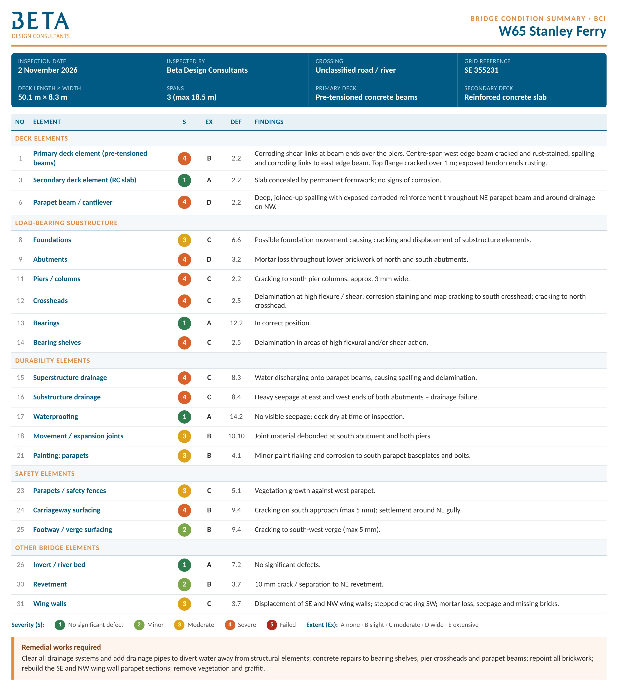
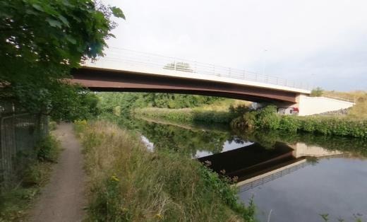
W65 Stanley Ferry carries an unclassified road over the river on three spans, with a longest span of 18.5 m and a deck approximately 50 m long and 8.3 m wide. The deck is made of pre-tensioned concrete beams with a reinforced concrete slab cast on permanent formwork, supported on reinforced concrete piers and crossheads and on brick abutments and wing walls.
BDC inspected W65 and recorded its condition on the BCI form, summarised in Figure 13. Our inspection gave several elements a severity of 4, meaning a severe defect where a significant loss of function could be expected:
|
Element |
S / Ex |
Finding |
|
Primary deck (pre-tensioned beams) |
4B |
Joined-up deep spalls exposing shear links and main bars, with corroding links at the beam ends over the piers. A cracked and rust-stained edge beam, and rusting exposed tendon ends on some beams |
|
Parapet beams |
4D |
Deep, joined-up spalling with exposed and corroded reinforcement throughout the north-east parapet beam and around the drainage on the north-west |
|
Piers and crossheads |
4C |
Cracks of about 3 mm in the south pier columns, with delamination, corrosion staining and map cracking to the crossheads |
|
Abutments |
4D |
Mortar loss throughout the lower brickwork of both abutments |
|
Drainage |
4C |
Water discharging onto the parapet beams and causing spalling, and heavy seepage at the ends of both abutments indicating drainage failure |
|
Foundations |
3C |
Possible foundation movement causing cracking and displacement of substructure elements |
|
Wing walls and revetment |
3C |
Displacement of the north-west wing wall, stepped cracking in the mortar joints and a 10 mm separation in the north-east revetment |
|
Carriageway |
4B |
Cracks up to 5 mm on the south approach and settlement around a drainage gully |
BDC therefore recommended clearing the drainage systems and adding drainage pipes to divert water away from the structural elements, together with concrete repairs to the parapet beams, crossheads and bearing shelves, repointing of the brickwork, rebuilding of the wing wall parapets, and removal of vegetation and graffiti.
W65 was inspected from a MEWP so that the beam ends, crossheads and bearing shelves could be examined at touching distance. On the bridge itself, the council allows the carriageway to be reduced to a single 3.5 m lane under vehicle-operated signals between 09:30 and 15:30, with a 1.5 m footway maintained at all times.
8. Reporting and Communication
A PI report is prepared for each structure on the client's template. It includes the completed BCI form, a description of each element, a photographic record of the defects found, and recommendations for maintenance, repair or further investigation.
Any defect that could affect public safety or the load-carrying capacity of a structure is reported to the client by phone and email on the day it is found, with photographs, before the full report is issued. Every report is checked and signed off by a Chartered Engineer before it is sent to the client.
Site inspections and report writing run in parallel, with an office team preparing the reports while the site team continues through the programme. Regular progress updates are issued to the client throughout the commission.
9. Project Outcome
The commission gives Wakefield Council an up-to-date and consistent record of the condition of 50 of its highway structures. Recording every structure to the same BCI method allows the council to compare the structures across its stock and to prioritise maintenance and capital spending where it is most needed.
By grouping the inspections by access method, limiting confined space entry to the structures where it is essential and keeping traffic management to a small number of planned days, BDC has been able to deliver the programme safely while keeping disruption to the public to a minimum.
The project demonstrates how careful planning, appropriate access methods and clear, consistent reporting support the long-term management of an ageing highway structures portfolio.
10. Beta Design Consultants Capability
Beta Design Consultants provides specialist structural engineering services for the inspection, assessment, repair and strengthening of existing structures and infrastructure.
The Wakefield project demonstrates BDC's ability to deliver a large inspection programme from start to finish: desk study, programming, safety planning, confined space and specialist access, condition scoring and repor
Related projects
BP GF Gas Plant Asset Integrity and Refurbishment
Read More
Bus Depot Electrification Harrow
Read More
Stage 50 Wycombe Film Studios Village
Read More
Stage 50 Bovingdon Airfield Studios
Read More
Concept Design of Cité Administrative Koloma
Read More
Structural Assessment of Henley Masonry Arch Bridge
Read More
Peckham Arch Condition Survey & Life Extension Consulting Services
Read More
Pembroke Road Footbridge - Structural Investigation & Strengthening
Read More
Concept Design of Sedhiou Bridge and Roads Network
Read More
Wycombe Air Park- Data Centre
Read More
Nant Melyn Bridge Inspection for Assessment
Read More
Clee Hill NATS Radar Tower
Read More
Burrington NATS Radar Tower
Read More
Hartlepool Solar Farm
Read More
Yeading Lane Bridge – Structural Assessment and CFRP Strengthening
Read More
Bus Depot Electrification – TfL Edgware Bus Depot
Read More
Mount View Road Bridge – Structural Strengthening and Remedial Works
Read More
Action Court Warehouse Extension
Read More
CFRP and HPC Concrete Strengthening for Brindleyplace
Read More
Leisure Swimming Pool House Design
Read More
BP Deep Water Sump Assessment and Concrete Repair Design
Read More
Planning Application for Three Story Residential Building
Read More
BP Heater Foundation Concrete Repair
Read More
Fulham Palace Road Temporary Works Design
Read More
Value Engineering for Warehouse and Office Building
Read More
Harwell Campus-Concrete Strengthening
Read More
Kennedy Institute Extension - Flat Slab Punching Shear Strengthening
Read More
Polybags Ltd Warehouse Extension in Lyon Way
Read More
Structural Repairs of a Listed Building
Read More
One West Point – Design of Support System for Cladding
Read More
Orchard House – RC Column Strengthening using CFRP
Read More
Structural Design of 3 Storey Building
Read More
Queens Rise- Steel Structure Connection Design and Detailing
Read More
Coast Drive Visitor Centre, Watersport and Beach Huts
Read More
Northside Garages Structural Investigation
Read More
RAAC Investigation and Structural Strengthening
Read More
Spire Academy (Horizon Academy) Car Park Refurbishment
Read More
United Downs Deep Geothermal Power Plant
Read More
Sprinkler Tank Base Design within Existing High-Rise Residential Towers
Read More
Planning Permission for 21 Boston Road Townhouse Conversion
Read More
Brentford Waterfront Block B and C Temporary Works Design
Read More
Brentford Waterfront Block K Temporary Works Design
Read More
Engine Yard Punching Shear Slab Strengthening
Read More
CPS House Jacketing to Strengthen RC Beams
Read More
BP GF Gas Plant – Slug Catcher Foundation Walls RC Repair
Read More
Helmsley Place-Steel Connections Design and Detailing
Read More
Planning Permission for New Warehouse, Ealing
Read More
Three Story Warehouse Steel Structure Design
Read More
Planning Permission for a Basement in a Conservation Area
Read More
London Hippodrome Roof Extension – Structural Design and Detailing
Read More
Unit 6-7 Queensmere Shopping Centre – Retail Units Conversion
Read More
St Peter’s Hospital Staff Accommodation, Piled Rafts Design
Read More
Grove Park Gardens 4 Storey Residential Development
Read More
LABSA Sulphonation Plant Erbil
Read More