Hartlepool Solar Farm
Project Summary
Sector: Renewable Energy / Infrastructure
Location: Worset Lane, Hartlepool, County Durham, United Kingdom
Project Type: Ground-Mounted Solar Photovoltaic Installation
Project Role: Independent Structural Assessment and Engineering Advice
Services Provided
- Independent Structural Assessment and Design Review
- Site Inspection and Engineering Observations
- Structural Analysis and SCIA Engineer Modelling
- Wind Loading and Wind-Tunnel Data Review
- Steelwork, Member Stability and Connection Assessment
- Solar Panel Restraint and Fixing Review
- Pile Foundation and Geotechnical Assessment
- Engineering Verification and Recommendations
1. Background
|
Sector |
Renewable energy / solar PV infrastructure |
|
Location |
Worset Lane, Hartlepool |
|
Role |
Independent structural assessment and engineering advice |
|
Methods |
Site observations · document review · SCIA Engineer modelling · foundation review |
|
Deliverable |
Independent assessment report and recommendations |
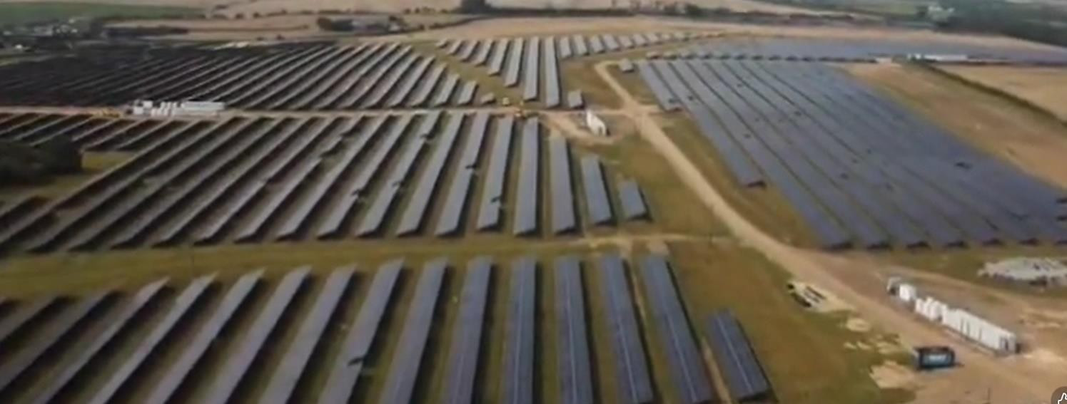
Beta Design Consultants (BDC) was appointed to undertake an independent structural assessment of a ground-mounted solar photovoltaic installation at Worset Lane, near Hartlepool. The commission involved a multidisciplinary review of the mounting structures and supporting foundations, combining site-based observations, design-document review and advanced structural analysis.
The solar farm is situated in a relatively open landscape close to the North Sea coast. In this setting, the design and performance of lightweight photovoltaic support systems depend on the coordinated consideration of wind actions, structural member behaviour, connections and ground conditions. The assessment provided an independent technical basis to inform the project team’s engineering decisions and future verification activities.
BDC’s role was to review the available structural information and assess the solar array support systems as an integrated engineering assembly. The appointment was an assessment and advisory commission; it was not a contract for construction or implementation of any subsequent works.
2. Engineering Context and Design Considerations
Large-scale ground-mounted photovoltaic installations involve repeated structural assemblies distributed across a substantial site. Although individual frames are relatively lightweight, their overall engineering performance relies on consistent load paths, dependable connection detailing and an appropriate understanding of foundation behaviour.
Wind Exposure and Structural Performance
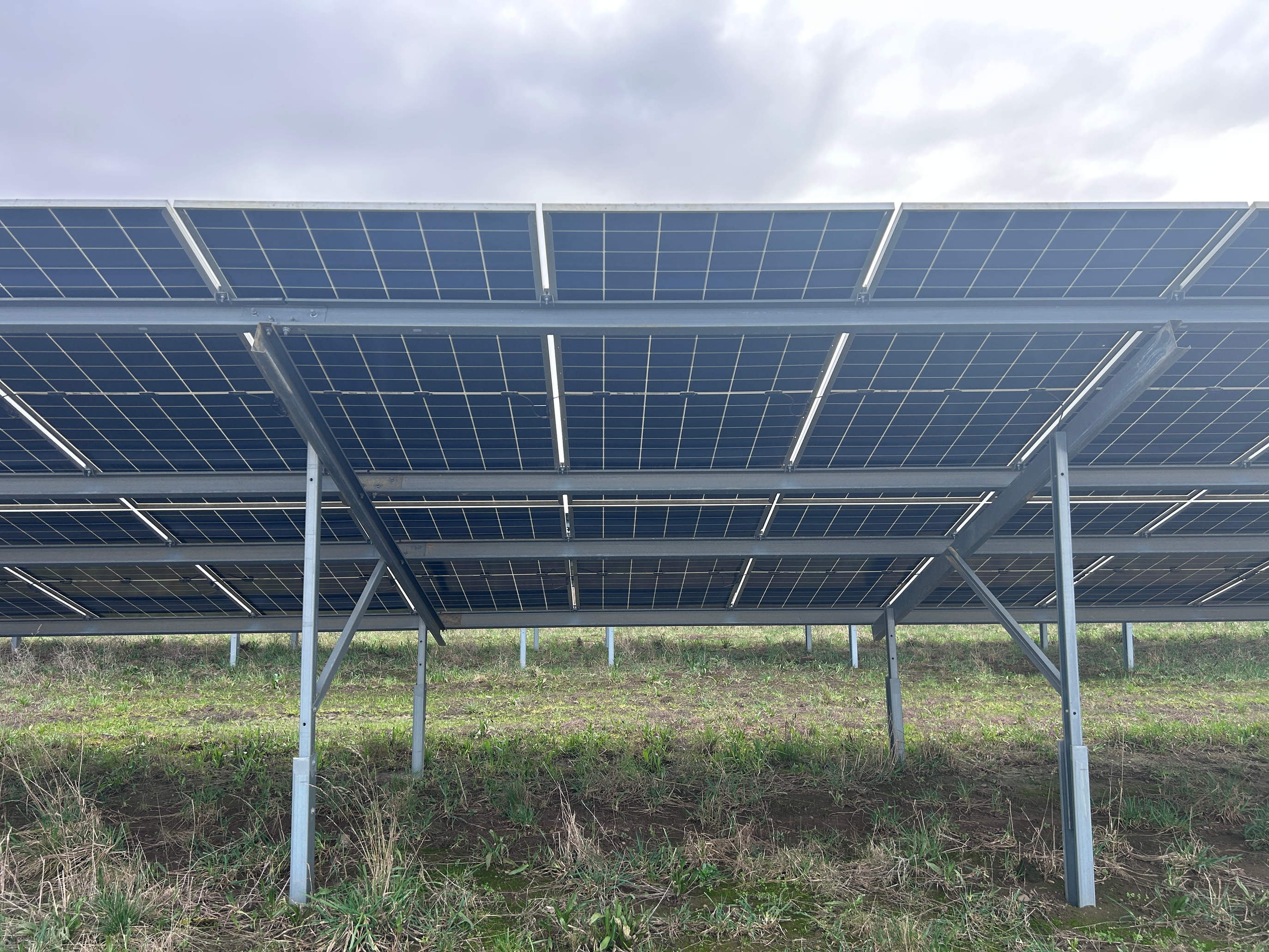
Solar PV tables behave as open, inclined structures exposed to variable wind pressure and uplift. Their structural assessment therefore requires careful interpretation of wind actions, the geometry of panel arrays and the interaction between primary supports, secondary members and connections.
For the Hartlepool project, BDC considered the applicable wind-loading framework and the influence of representative table configurations. This helped establish a coordinated basis for evaluating the mounting system under relevant design conditions. Wind tunnel testing data provided by the client was compared with the applicable Eurocodes guidance on wind loading to inform the design.
Integration of Structural Components
The assessment considered the performance of the complete support arrangement rather than treating each element in isolation. Key interfaces included the photovoltaic modules, purlins, support posts, clamps, bolted connections and embedded foundations. The engineering review examined how forces are transferred through these components and how their behaviour can influence the overall system.
Ground Conditions and Foundation Behaviour
The support structures are founded on embedded steel piles, making the relationship between structural loads and ground response a key consideration. BDC reviewed the available geotechnical and pile-related information alongside the structural assessment, considering foundation resistance, movement and the assumptions used to represent soil–structure interaction.
3. Scope of Services
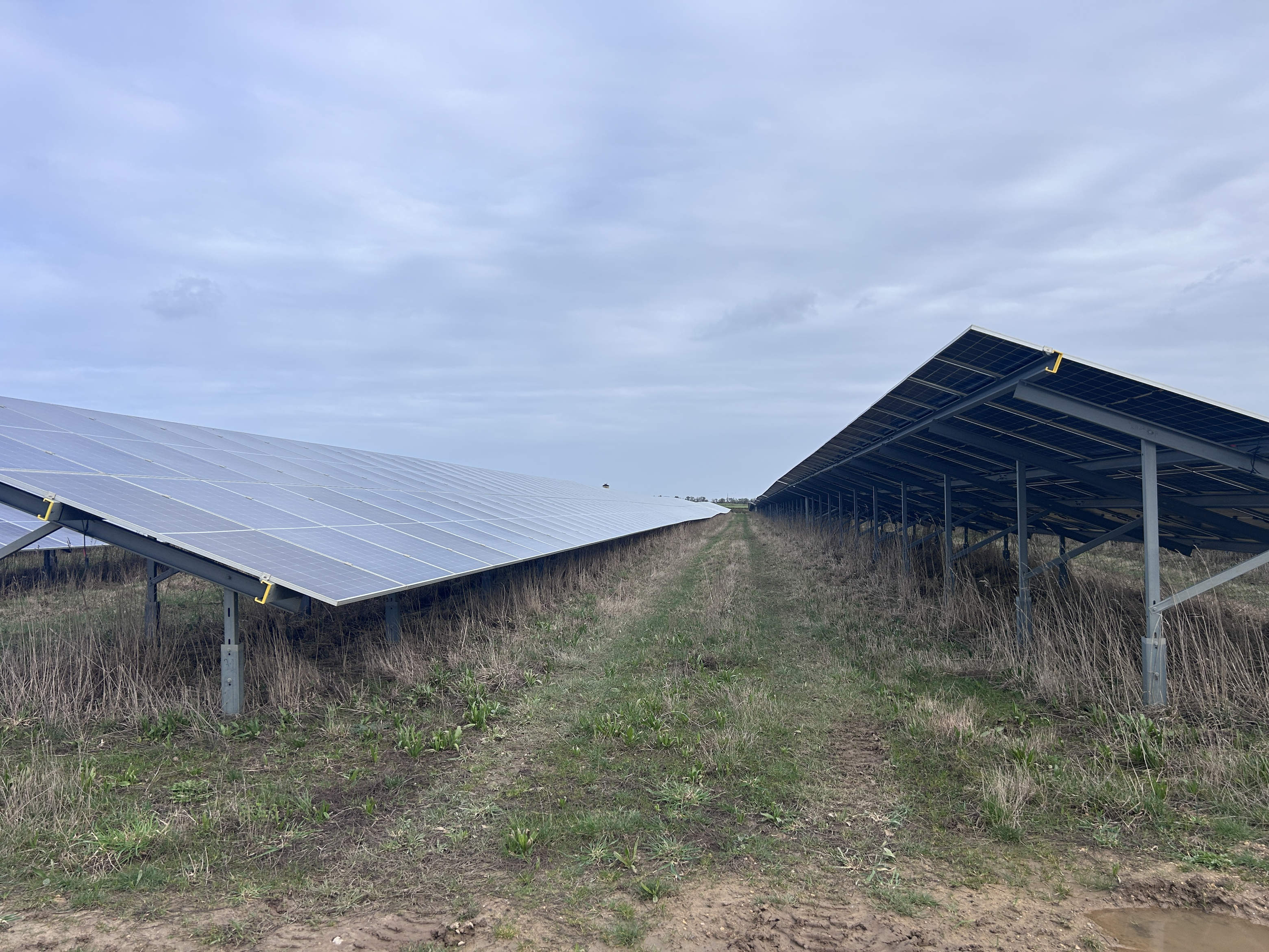
BDC’s independent assessment brought together the following workstreams:
- Review of available structural design drawings, specifications, calculations and supporting technical records.
- Site visit and engineering observations to inform the desktop assessment.
- Review of environmental actions, including wind loading relevant to ground-mounted PV arrays.
- Three-dimensional structural modelling of representative solar table configurations using SCIA Engineer.
- Assessment of structural members, support frames, connections and panel restraint arrangements.
- Review of pile foundations and available ground investigation and pile-testing information.
- Preparation of an independent technical assessment and coordinated engineering recommendations.
4. Site Investigation and Engineering Review
As part of the independent assessment, BDC undertook a site visit and reviewed available drawings, design calculations, specifications and supporting technical records. The site observations helped inform the assessment of the installed solar mounting arrangements, including the relationship between photovoltaic panels, steel support members, connections and embedded piles.
The engineering review considered the structural system as a whole, tracing the transfer of actions from the modules through clamps, purlins, rafters and support posts to the foundations. This approach provided context for the subsequent analytical modelling and helped identify the design information needed to assess member behaviour, connection performance and overall stability.
Available ground investigation and pile-testing records were also reviewed to inform the assessment of foundation behaviour. The investigation information included 20 mechanically excavated trial pits extending to a maximum depth of approximately 3 m. BDC considered this evidence alongside pile embedment, ground parameters, potential lateral movement and the structural reactions transmitted to the supports.
The site inspection and document review were components of an independent engineering assessment, rather than a separate ground-investigation or construction commission. Their purpose was to establish an evidence-based understanding of the existing installation and to inform recommendations for further design verification where appropriate.
5. Structural Analysis and Engineering Assessment
Support arrangement and member continuity
The reviewed mounting arrangement transfers actions from photovoltaic modules through clamps and purlins to rafters, vertical supports and embedded piles. Each panel is supported by two purlins and secured using four clamps, as described in the assessment. The engineering review considered the contribution of these interfaces to the complete load path, rather than treating individual components in isolation.
For the analysis, purlins were modelled as continuous over rafter supports, and rafters as continuous over their column supports. This approach accounts for the bending effects that develop at intermediate supports. Member stability was also reviewed using relevant unrestrained lengths, including lateral restraint provided by adjacent framing elements.
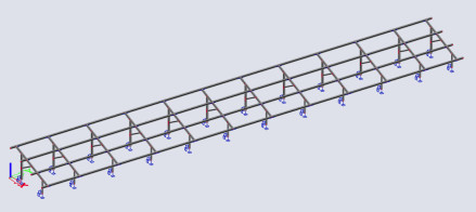
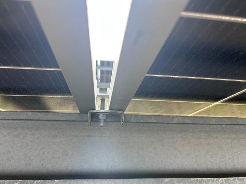
BDC used SCIA Engineer to develop three analytical models representing different external solar panel-table configurations. The review addressed both ultimate limit state (strength and stability) and serviceability limit state considerations.
The frame review considered ultimate-limit-state strength and serviceability performance, including bending, shear, axial effects and deflection. Particular attention was given to member continuity over supports, the contribution of bracing and lateral restraint, and the way local connection behaviour influences the performance of the wider support system.
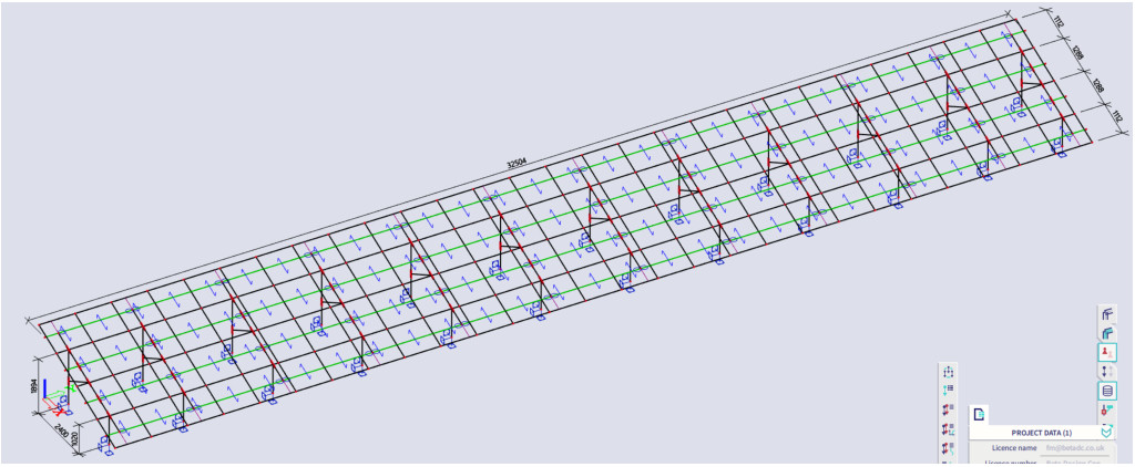
The assessment identifies two solar-table configurations (14 × 2 and 28 × 2 panels). The 28 × 2 arrangement was selected for the reported structural analysis because it has a larger span between supports; the illustrated model represents an external panel-table location. The principal structural elements comprise purlins, rafters, front and rear vertical supports, and piles.
The technical assessment considered the following interrelated topics:
- Wind loading and the application of appropriate design assumptions for open-canopy photovoltaic structures.
- Strength, stability and serviceability of the steel mounting frames and purlins.
- Behaviour of bolted connections and panel fixing arrangements within the overall structural system.
- Transfer of loads through support posts to the embedded pile foundations.
- The relevance of ground conditions, pile embedment and lateral response to foundation verification.
- Material durability, construction tolerances and installation quality as part of long-term asset management.
The review combined analytical modelling with professional engineering judgement and available site evidence. This integrated approach is particularly important for repeated modular structures, where consistency of design assumptions and installation records contributes to reliable long-term performance.
6. Wind Engineering and Design Verification
Loading scenarios and design actions
The numerical assessment considered permanent actions from the supporting steelwork and photovoltaic modules, alongside environmental actions from snow and wind. Wind was examined in both downward-pressure and uplift (suction) conditions. Eight wind-loading cases were developed to assess representative panel positions and coefficient approaches; the resulting actions informed the structural model and the selection of governing combinations for strength and serviceability review.
The loading methodology drew on both code-based open-canopy pressure coefficients and project-specific wind-tunnel information. This enabled a coordinated comparison of design assumptions, load direction and the way actions transfer through the panel support assembly.
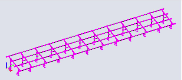
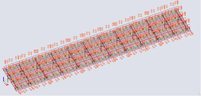
Wind is a significant design action for ground-mounted solar arrays because panel inclination, edge conditions and exposure influence both pressure and uplift. BDC reviewed the wind-loading approach with reference to relevant Eurocode provisions and the available project-specific information. The engineering team compared wind actions derived from Eurocode guidance with project-specific wind-tunnel information provided by the client. Eight analysis load cases were developed to explore representative pressure and uplift/suction conditions, including the relevant combined actions. This comparison informed the verification methodology without assuming that a single loading scenario represented the whole installation.
For open-canopy PV structures, the distribution of pressure and suction can vary between exposed edges and more sheltered table positions. The review therefore considered representative loading zones and combinations, with attention to how uplift affects panel fixings, supporting members and the overall load path. A consistent, traceable wind-design approach helps align the analysis of each component.
The assessment considered the importance of a clearly documented wind design basis, representative load combinations and consistent application of assumptions across structural components. These considerations provided a framework for the independent verification of the solar mounting system without relying solely on isolated member checks.
7. Foundation and Geotechnical Coordination
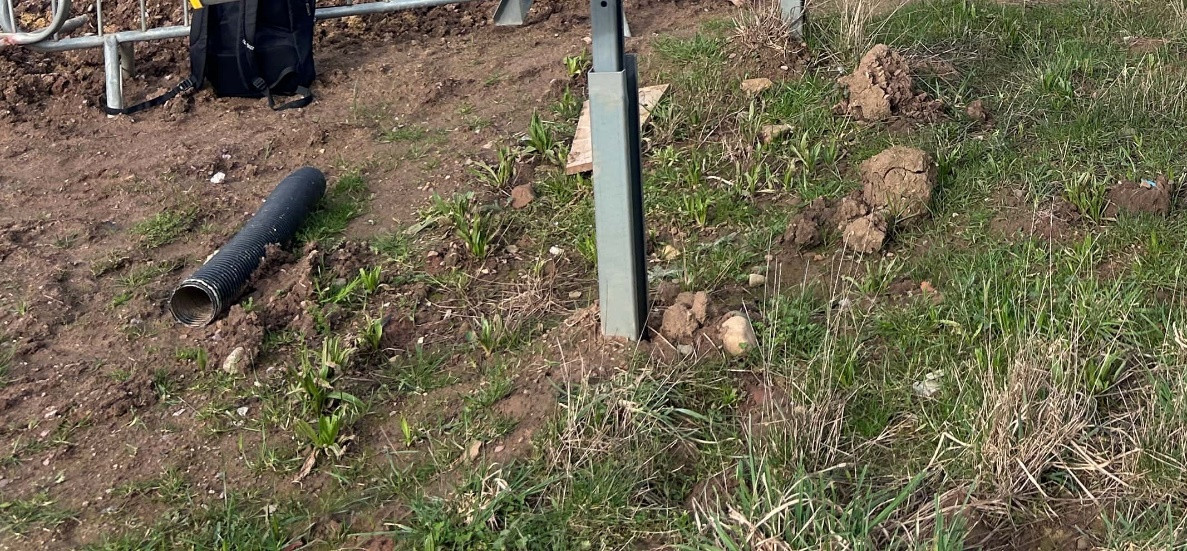
BDC reviewed the available ground investigation information and pile-testing evidence to understand the relationship between site conditions, embedded steel piles and the solar table support structures. The investigation records included 20 mechanically excavated trial pits, extending to a maximum depth of approximately 3 m. The assessment considered how ground parameters and pile–soil interaction inform the verification of structural reactions, foundation behaviour and serviceability. This review formed part of the integrated structural and geotechnical assessment, rather than a separate ground-investigation commission.
The geotechnical review considered how pile embedment, soil parameters and lateral movement criteria relate to the reactions transferred from the steel support frame. Ground investigation and pile-test records provide useful supporting evidence, while final foundation verification requires those records to be assessed alongside the adopted structural loads and design assumptions.
By bringing structural and geotechnical considerations together, the assessment supported a coordinated understanding of how the mounting system transfers forces into the ground and what supporting evidence is appropriate for design verification.
8. Engineering Recommendations and Project Value
The commission culminated in an independent technical report and a structured set of engineering recommendations. The recommendations addressed the documentation of design assumptions, verification of structural components and connections, coordination of foundation information and consistent technical quality assurance.
The recommendations also addressed the relationship between design calculations and installation evidence. A coordinated verification process can include documented connection capacities, defined alignment and fixing tolerances, confirmation of specified materials, and inspection records that demonstrate how the design intent is translated into the installed system.
The resulting assessment provided the project team with an informed basis for reviewing the design evidence, planning further verification where appropriate and making decisions about the long-term performance of the solar PV infrastructure. These recommendations are presented as advisory outputs of the assessment; the source documents do not establish that any subsequent measures were implemented.
9. Coordinated Performance Improvement Framework
The assessment translated its technical review into a coordinated programme of recommendations. These are proposed verification and quality-assurance measures, rather than confirmation of completed remedial works.
- Wind design basis — Document the selected Eurocode or wind-tunnel approach, relevant canopy zones, aerodynamic coefficients, assumptions and load combinations.
- Structural frame — Verify strength and serviceability of purlins and framing under combined actions, and consider restraint, bracing or other strengthening measures where justified by the detailed design.
- Panel restraint and connections — Substantiate uplift and sliding resistance, engagement, tolerances and connection detailing through suitable design evidence and inspection criteria.
- Pile and soil coordination — Reconcile structural reactions with ground parameters, pile testing, embedment design and lateral displacement criteria.
- Installation assurance — Define measurable acceptance checks for bolt torque, alignment, setting-out, bracing and inspection records.
- Durability and traceability — Confirm material specifications and corrosion protection, with traceable records from design requirements through procurement and installation.
- Engineering close-out — Provide for responsible designer review, documentation of agreed changes and verification against approved design information.
Engineering assessment methodology
The assessment combined a site inspection, review of technical records, comparison of code-based and project-specific wind information, eight representative load cases, three SCIA Engineer structural models, and coordinated review of connections, piles and ground data. Together, these workstreams provided a documented basis for engineering recommendations.
Integrated engineering review
|
Assessment element |
Scope of review |
|
Site evidence |
Inspection observations, available drawings and supporting design records |
|
Wind actions |
Review of code-based and project-specific wind-loading approaches |
|
Structural verification |
SCIA modelling, member actions, stability and serviceability |
|
Connections |
Panel restraint and connection behaviour within the load path |
|
Foundations |
Ground investigation records, pile evidence and soil–structure interaction |
|
Engineering outputs |
Coordinated assessment and recommendations for further verification |
10. Expected Project Benefits
|
Improvement area |
Expected benefit |
|
Wind-load definition |
A transparent, traceable basis for design actions and structural checks. |
|
Frame verification |
Better understanding of member strength, deflection, and restraint needs. |
|
Clamp and connection checks |
More reliable evidence of panel retention and connection resistance. |
|
Pile-soil review |
Design assumptions better aligned with ground information and test evidence. |
|
Installation quality records |
Improved consistency, inspection traceability, and verification of workmanship. |
|
Durability controls |
Earlier identification of corrosion concerns and clearer material compliance records. |
These are anticipated benefits, subject to implementation and verification of the proposed engineering measures; they should not be interpreted as confirmed post-construction outcomes.
11. Engineering Lessons and Wider Application
The assessment reinforces the importance of reviewing solar tables as integrated systems: modules, clamps, purlins, bracing, posts, piles and ground all contribute to the load path. It also highlights the value of consistent wind assumptions, documented proprietary-component performance, coordinated geotechnical evidence and practical installation acceptance criteria.
12. Outcome
BDC delivered a multidisciplinary independent structural assessment of the Hartlepool solar PV mounting systems, supported by site observations, analytical modelling and a review of available structural and ground information. The work brought together wind engineering, structural steelwork behaviour especially light gauge steel, connection assessment and foundation considerations within a single technical review.
The project illustrates the importance of robust design verification for renewable-energy infrastructure and demonstrates BDC’s ability to provide detailed, practical engineering advice across structural and geotechnical disciplines.
13. Beta Design Consultants Capability
Beta Design Consultants supports renewable-energy and infrastructure projects through independent structural reviews, advanced numerical analysis, foundation engineering and multidisciplinary technical advice. Our approach combines detailed engineering assessment with a clear understanding of project delivery, helping clients make informed decisions about the performance and resilience of their assets.
Related projects
BP Deep Water Sump Assessment and Concrete Repair Design
Read More
BP Heater Foundation Concrete Repair
Read More
BP GF Gas Plant Asset Integrity and Refurbishment
Read More
BP GF Gas Plant – Slug Catcher Foundation Walls RC Repair
Read More
Bus Depot Electrification Harrow
Read More
Stage 50 Wycombe Film Studios Village
Read More
Energy from Waste Plant - Process Water Drainage Design
Read More
Stage 50 Bovingdon Airfield Studios
Read More
Concept Design of Cité Administrative Koloma
Read More
Structural Assessment of Henley Masonry Arch Bridge
Read More
Peckham Arch Condition Survey & Life Extension Consulting Services
Read More
Pembroke Road Footbridge - Structural Investigation & Strengthening
Read More
Concept Design of Sedhiou Bridge and Roads Network
Read More
United Downs Deep Geothermal Power Plant
Read More
Wycombe Air Park- Data Centre
Read More
Nant Melyn Bridge Inspection for Assessment
Read More
Clee Hill NATS Radar Tower
Read More
Burrington NATS Radar Tower
Read More
Action Court Warehouse Extension
Read More
Brentford Waterfront Block B and C Temporary Works Design
Read More
Brentford Waterfront Block K Temporary Works Design
Read More
Leisure Swimming Pool House Design
Read More
Planning Application for Three Story Residential Building
Read More
Fulham Palace Road Temporary Works Design
Read More
Value Engineering for Warehouse and Office Building
Read More
Planning Permission for a Basement in a Conservation Area
Read More
Polybags Ltd Warehouse Extension in Lyon Way
Read More
One West Point – Design of Support System for Cladding
Read More
Structural Design of 3 Storey Building
Read More
Queens Rise- Steel Structure Connection Design and Detailing
Read More
St Peter’s Hospital Staff Accommodation, Piled Rafts Design
Read More
Grove Park Gardens 4 Storey Residential Development
Read More
Coast Drive Visitor Centre, Watersport and Beach Huts
Read More
Northside Garages Structural Investigation
Read More
RAAC Investigation and Structural Strengthening
Read More
Spire Academy (Horizon Academy) Car Park Refurbishment
Read More
Sprinkler Tank Base Design within Existing High-Rise Residential Towers
Read More
Planning Permission for 21 Boston Road Townhouse Conversion
Read More
Helmsley Place-Steel Connections Design and Detailing
Read More
Planning Permission for New Warehouse, Ealing
Read More
Three Story Warehouse Steel Structure Design
Read More
Kennedy Institute Extension - Flat Slab Punching Shear Strengthening
Read More
London Hippodrome Roof Extension – Structural Design and Detailing
Read More