Beta Design Consultants provide geotechnical engineering and structural engineering related to the design and checking of all types of earth retaining structures and retaining walls.
Types of Earth Retaining Structures we provide services for
Beta Design Consultants have supported their clients in designing new retaining walls/structures and assessing the various types of earth retaining structures that are commonly used in civil engineering and geotechnical applications. We ensure these structures are designed (or assessed if they are already built) to stabilize and support soil or other materials (e.g. water), preventing them from collapsing or sliding. Our consulting geotechnical engineers and structural engineers have designed and assessed the following most common types of earth retaining structures and retaining walls:
1. Gravity Walls:
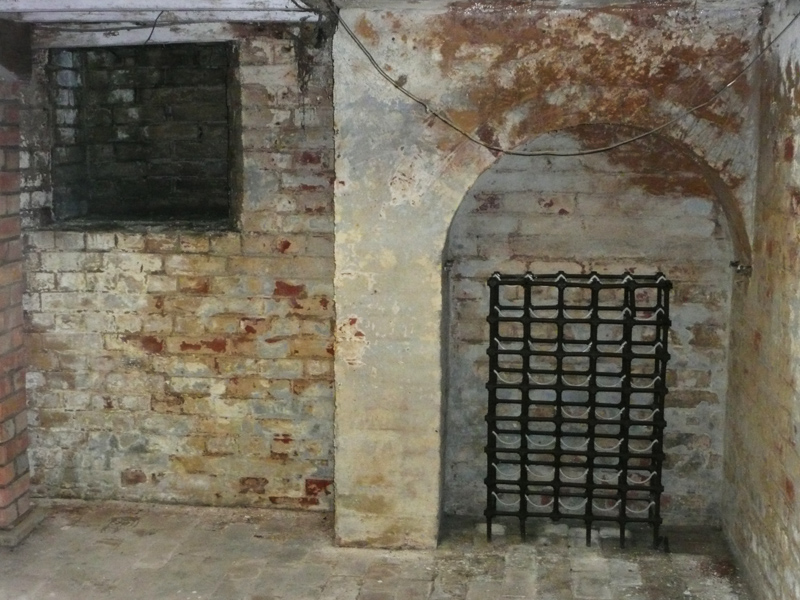
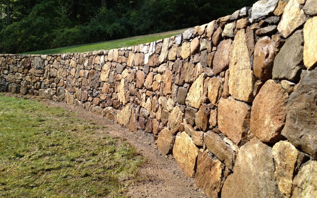
Gravity walls rely on their own weight to resist the pressure exerted by the retained soil. These structures are typically made of concrete or masonry (brickwork, blockwork or stone) and are suitable for relatively low retaining heights. They are often used in landscaping, garden walls, and small-scale applications such as low height cellars and basements. Gravity walls include mass concrete walls, masonry retaining walls (such as those used in historic properties below ground), rubble masonry walls (used in gardens or traditionally used all around the world).
The design and construction of gravity walls relies on the weight of the wall materials to have friction at the base to resist the applied forces. Historically, this technique developed empirically and masons and builders developed local rules for the width of the wall compared to its height.
Failure Modes of Gravity Walls:
Failure of such walls can happen when the weight of retained earth increases, for example if the retained height changes or if during the winter season excessive rainfall causes the retained earth to have much higher hydrostatic pressure on the wall that exceeds sliding or overturning resistance. Another factors that may cause the failure of gravity walls is the reduction in its resistance either due to erosion at the base or due to site conditions making friction coefficient less than the original (e.g. in very wet conditions).
For the above reasons, considering drainage of the retained earth is a crucial aspect in the design of construction of such walls and during their maintenance.
Inspections should focus not only on the structural condition but also on the condition of drainage and on factors that could undermine the wall.
Beta Expertise
Beta Design Consultants have been involved in the design, inspection and repair of gravity walls and the importance of regular maintenance and inspection can not be over-stated.
- We have assessed and recommended repairs for many existing gravity retaining walls. These walls pose a special challenge as they have been working for a long period and have stood the test of time but they may not be compliant with modern standards. Our approach when assessing them is to always make recommendations to make them stronger. Such measures include introducing anchors, improving drainage and even introducing strengthening if required.
- In one case, the leak of a nearby water pipe causes a gravity retaining wall to completely collapse causing major damage to a commercial and residential property and a massive disruption in a busy high street in London. We worked closely with the client and contractor to seek local authority approval for the proposed measures to repair this dangerous structure.
2. Cantilever Walls:
Cantilever walls are reinforced concrete walls that use a base slab and an upright stem to resist the lateral pressure of the soil. The stem can be thicker at the base and tapers towards the top in some cases, allowing it to act as a cantilever beam. These walls are commonly used in medium to high retaining wall heights and are more structurally efficient compared to gravity walls. Beta Design Consultants specify these walls in basements, or to underpin basements. They are also used in water retaining structures such as oil and gas sumps, liquid storage tanks underground and swimming pools.
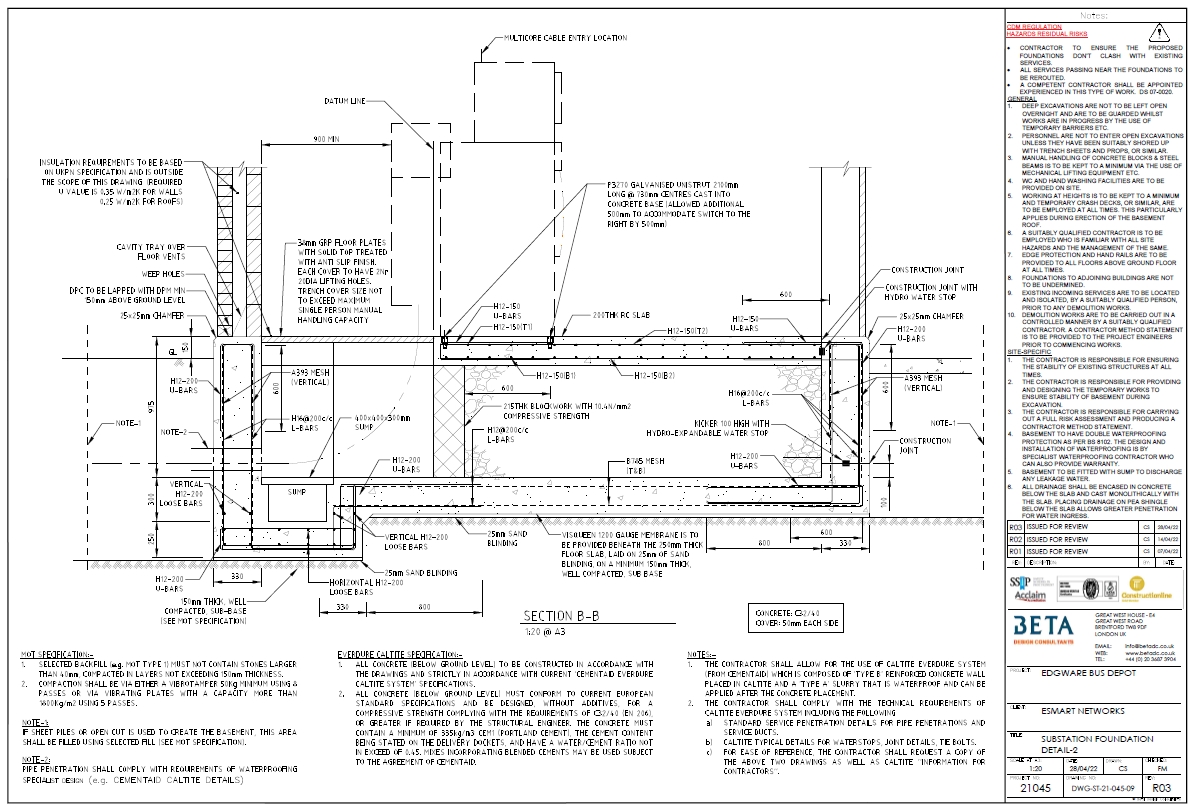
The design and construction of these walls relies on making the connections of the base-wall a rigid one so it can resist lateral forces (in bending and shear) and limit deflection of the wall. In some cases, the top of the wall has to be propped to get the wall to work safely. As such detailing of the rebar and correct installation of the rebar is crucial to the correct construction.
Failure Criteria of Cantilever Walls
The failure of these walls can be caused by a variety of reasons including:
- Poor or inadequate site investigation, inadequate site assessment or topo survey (incorrect levels used), insufficient information about existing site conditions, utilities, drainage, services.
- Mistakes during design such as the lack of specification for water-stopping details, waterproofing details, crack width control, durability specifications for concrete, correct specification for concrete cover and rebar, correct detailing of rebar, proper communication of temporary works requirements.
- Mistakes in the temporary works design or installation – as an example if propping is required at the top of the wall and the contractor fails to maintain this propping when moving from the temporary condition to the permanent condition.
- Poor placement of concrete so the cover is not maintained, poor placement and honey combing, failure to install waterproofing correctly, failure to install drainage correctly, failure to compact soil below the base, failure to install rebar as intended, failure to have a shear key or shear thickening as noted on drawings, failure to install temporary works and follow agreed method statement.
- Poor maintenance and operation of the walls. For example excessive loading through extra water pressure if drainage is not maintained or via burst water pipes, corrosion and concrete deterioration if water is not drained, excessive surcharge on retained earth beyond design loads, poor inspection or lack of delaying discovery of defects and their rectification, delayed maintenance causing a vicious cycle of deterioration where exposure to elements leads to corrosion that leads to wider cracking causing even more corrosion.
Beta Expertise
Beta Design Consultants has designed, assessed and repaired many cantilever walls including
- a large number of retaining walls in flood prevention schemes (Pendle Wate FPS and Braid Burn FPS), these needed to be re-assessed for a new water level considering climate change.
- A large number of retaining walls designed in oil and gas facilities (sumps, storage tanks).
- Maintenance of oily water sumps and process water sumps in oil and gas facilities.
- Inspection (visual and NDT) and repair design of retaining walls in multi-storey underground car parks that have retaining walls retaining earth or wet earth.
- Design of new retaining walls for basements and underpinning.
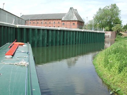
3. Sheet Pile Walls:
Sheet pile walls are made of interlocking steel, vinyl, or concrete sheets driven vertically into the ground. These sheets create a continuous wall that resists lateral soil pressure. Sheet pile walls are commonly used in waterfront structures, deep excavations, and temporary retaining applications.
The design and construction of these sheet piles is based on one of few structural configurations:
- Free cantilever: where the embedded part creates the anchorage of the wall and the rest acting as cantilever resulting in the tip potentially deflecting excessively sideways so this is only suitable where a prop is not possible or is not needed as it requires the wall section to be strong enough to resist all the applied pressure without any propping or temporary works.
- Propped cantilever: where the embedded part creates the anchorage and a prop is provided at the top or at intermediate heights. This prop can be achieved with the aid of walers or capping beam that are then restrained at certain spacing. The restraint is either using props or using anchors embedded in ground (soil anchors).
Benefits of steel sheet pile walls compared with other retaining wall methods such as cantilever retaining walls or embedded piled walls include:
- Speed of construction and programme savings of 20-30%
- Lower overall costs (refer to UK SCI Publication Steel Intensive Basements)
- Greater safety and improved site management
- Ease of maintenance
- Minimal land take (footprint)
Failure of Sheet Pile Walls include serviceability and ultimate limit state modes.
SLS failure modes of sheet pile walls include:
- movement of ground or of a retaining structure that would cause damage and cracking in
- adjacent buildings, loss of performance of drainage or affect aesthetics of wall
- unacceptable leakage through or beneath the wall, or change to the flow of groundwater
- unacceptable transport of soil grains through or beneath the wall
- structural durability (e.g. corrosion, section loss)
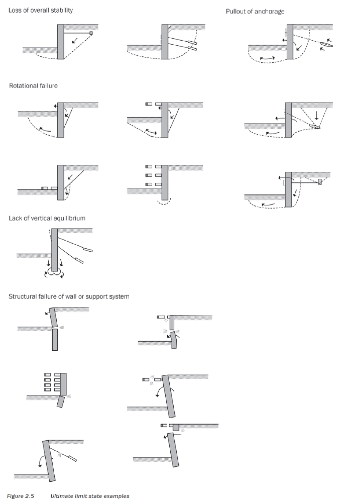
USL failure modes of sheet pile walls include:
- loss of overall stability
- failure of a structural element or failure of a connection between elements i.e. strut failure, bending stress and or shear failure in the sheeting
- combined failure through the ground and structural elements
- failure by forward rotation, translation, or lack of vertical equilibrium of the wall
- penetration failure
- toe failure
- foundation heave failure in soft clays
- hydraulic failure (i.e. piping in cohesionless soils with high external groundwater table)
- passive failure of soil below stage excavation level or final formation level.
- accidental unintended loading is applied to a structure such as surcharge overload, temporary works damage or burst water main.
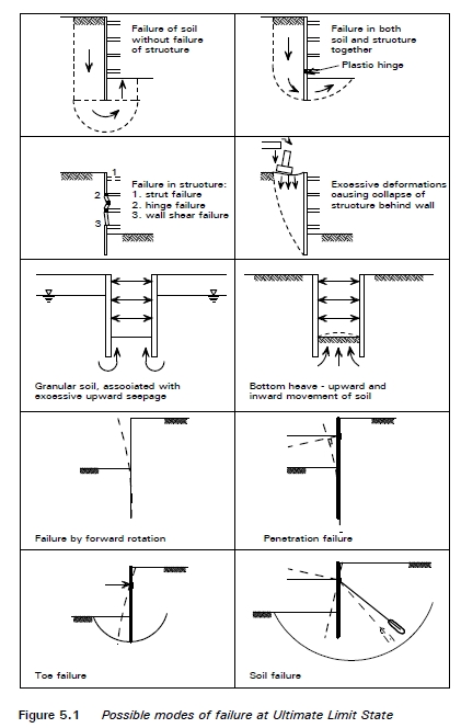
Model of ULS Failure in Sheet Pile Walls
Beta Expertise
Beta Design Consultants has designed and assessed many sheet pile walls including
- A large number of sheet pile walls assessed as part of flood prevention schemes (Pendle Wate FPS and Braid Burn FPS), these needed to be re-assessed for a new water level considering climate change.
- A large number of sheet pile walls assessed in various ports and in some cases these were subject to erosion effect for tidal effects or from operation loading. Some of these quays were receiving additional loading and we made a proposal to support new loading and strengthen existing walls via anchors.
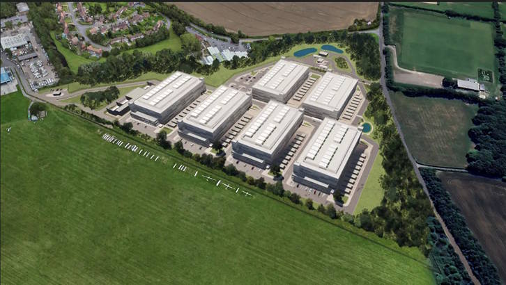
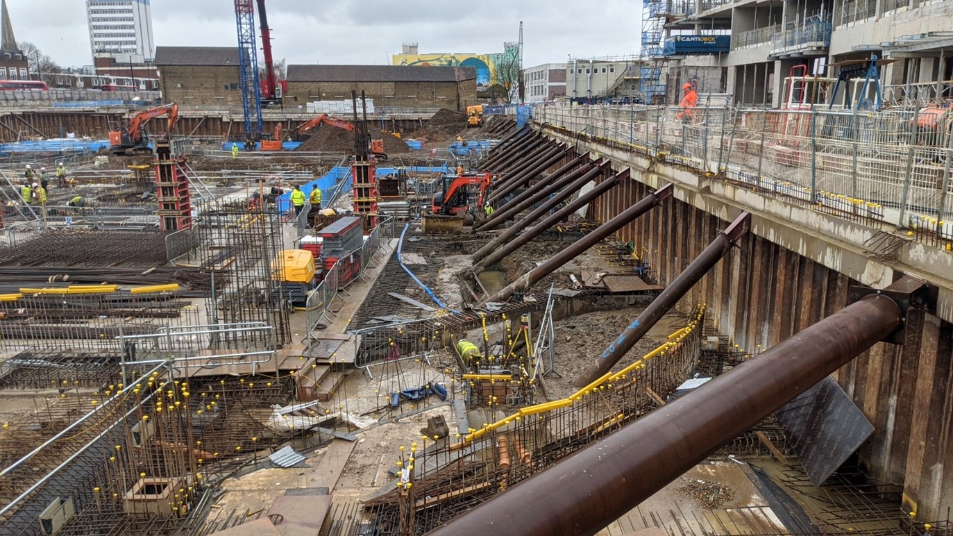
- Design of new retaining walls for basements. This included three large blocks in Brentford Waterfront project where the basement was created in exposed sheet piles and propped temporarily using raking props designed by Beta and propped permanently using the ground floor slab.
Prevention Scheme
4. Embedded Retaining Walls (piled):
Beta Design Consultants advise clients on the most suitable embedded piling wall solution based on various factors such as soil conditions, required wall strength, water tightness, and project specifications. A major factor is cost and in many cases the programme. In other cases, the installation difficulty and impact (noise, vibration, displacement, impact on adjacent properties) are all factors that need to be considered.
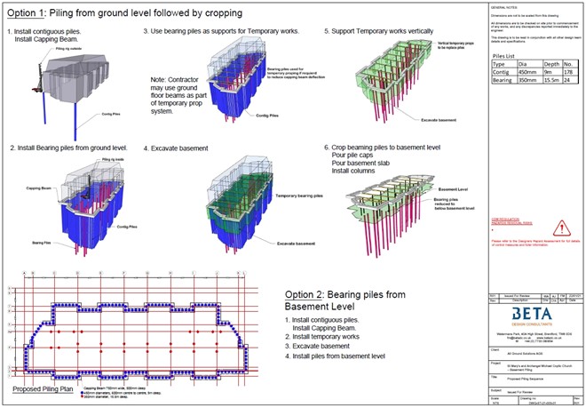
1. Contiguous Pile Walls:
Contiguous pile walls are formed by drilling or driving individual piles with minimal gaps between them. Contiguous piles are typically reinforced and filled with concrete. Contiguous pile walls are commonly used in urban areas and deep excavations where space is limited.
Contiguous piles are one of the most cost-effective embedded pile wall solutions. The piling rigs can be quite small allowing their use in restricted access locations. They are also some of the fastest to install. In cohesive soils such as London Clay, contiguous piles are naturally adapted to various depths and are very common in excavations and basement construction in London. In River Terrace locations, granular soil locations and especially if water table is above the excavation base, contiguous piles are not suitable unless the granular soil is mixed with clay/cohesive material and careful hydrology studies confirm filtration rates to be slow and measures are put in place on site are to control water seepage.
If basements cannot be created by underpinning and piling needs to be considered, contiguous piles are typically the natural choice for Beta Design Consultants when designing small to medium size basements where water table is not high. For larger basements, other options such as sheet pile walls may also need to be considered.
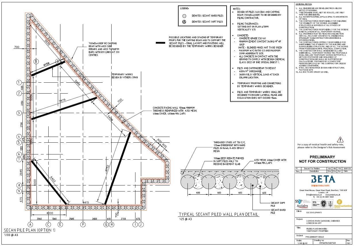
2. Secant Pile Walls:
Secant pile walls consist of intersecting piles that are constructed by drilling primary piles and then installing secondary piles between them. The primary (male) piles are typically made of concrete, and the secondary (female) piles are usually installed with less accuracy, allowing them to interlock with the primary piles. Secant pile walls are commonly used in situations where water tightness is required, such as in deep basements and underground structures. They are also used in making basements and excavations in sites with high water table (above excavation base) or where the retained earth is granular and hard to retain using contiguous piles.
Secant piles are more expensive and take more time to install compared to contiguous piles as they require more drilling, they require a guide wall and they require more materials. During the design, only the male pile is considered to resist applied forces while female piles are considered to pick up hydrostatic pressure and transfer to the male piles either side.
3. Tangent Pile Walls:
Tangent pile walls are created by driving or drilling individual piles adjacent to each other without any overlap or interlocking. The piles are installed at a tangent to each other, creating a continuous wall. Tangent pile walls are commonly used for deep excavations and temporary shoring and can be made of steel, concrete, or composite materials.
Tangent piles are used in similar site locations to secant piles but can be more effective and stiffer. Tangent piles are more expensive than secant piles and are usually chosen when the size of the secant pile (diameter) becomes too high and starts to take too much space that an alternative option is needed. Unlike the secant piles where only the male pile is taken to resist forces, the tangent piles allow a smaller diameter to be used as the touching piles are all hard and can thus resist loading resulting in a more stiff section compared to secant pile of same dia and depth.
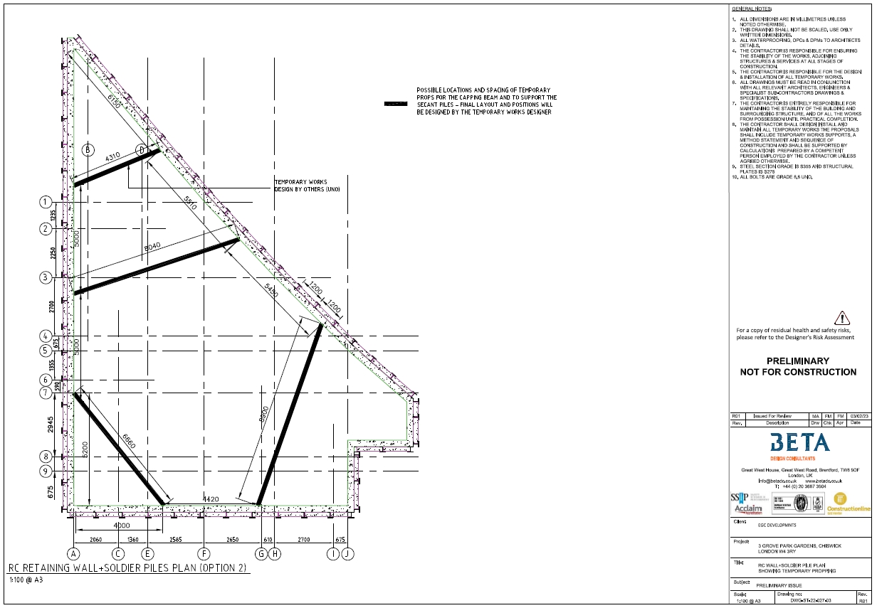
4. Soldier Pile Walls:
Soldier pile walls consist of vertical steel piles called soldier piles spaced at regular intervals, with timber lagging or reinforced concrete panels placed between them. The soldier piles provide support while the lagging or panels retain the soil. Soldier pile walls are often used in temporary shoring and can be constructed quickly and cost-effectively.
Soldier pile walls offer a very cost effective piling solution but they can be slower to build than other forms of piling as the installation of the lagging/precast planks may take time and add to the programme.
Failure Modes of Embedded Retaining Walls:
For embedded retaining walls, Beta Design Consultants engineers refer to the guidance of EC7 which lists the following considerations, where relevant:
- loss of overall stability
- failure of a structural element, such as a wall, anchor, waler or strut, or failure of the connection between such elements
- combined failure in the ground and in the structural element
- failure by hydraulic heave and piping
- movement of the retaining structure, which may cause collapse or affect the appearance or efficient use of the structure or nearby structures or services, that rely upon it
- unacceptable leakage through or beneath the wall OR unacceptable change in the groundwater regime
- unacceptable transport of soil particles through or beneath the wall
- failure by rotation or translation of the wall or its parts
- failure by lack of vertical equilibrium.
According to CIRIA 760 “Guidance on Embedded Retaining Walls Design”, Most failures occur due to inadequate design or inadequate control of the support to a wall in the temporary works condition. Wall failures are most likely to be caused by:
- Inadequate understanding of the geological and hydrogeological conditions, including soil properties and groundwater effects
- Poor design and construction details
- Poor standard of workmanship, particularly of support systems.
- Construction operations and sequences that result in earth pressures differing from those assumed in design.
- Inadequate control of construction operations, eg over-excavation of berms and formation, excessive surcharge loads from soil heaps and construction equipment.
5. Diaphragm Walls:
Diaphragm walls are constructed by excavating a trench and then installing reinforced concrete panels into the trench. The panels are typically interconnected to form a continuous wall that acts as a barrier against soil and groundwater. Diaphragm walls are often used in deep excavations, underground structures, and for providing watertight barriers.
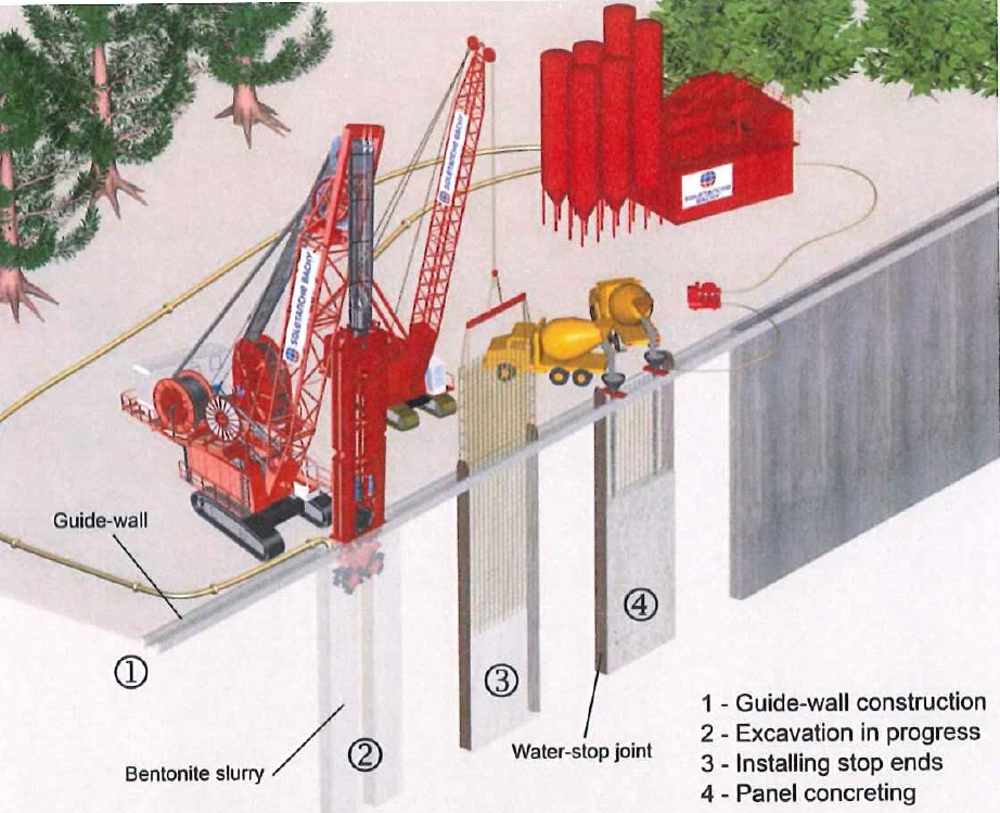
Diaphragm walls are a special type of retaining walls suited for specific application and require special design and construction expertise. Beta Design Consultants structural and geotechnical engineers have been involved in most of these applications, through construction services, temporary works design or geotechnical studies including:
- Deep Excavations:
Diaphragm walls are frequently used in deep excavations to provide temporary or permanent support. They can withstand high lateral earth and hydrostatic pressures, making them suitable for creating deep basements, underground parking garages, and subway stations.
- Retaining Walls:
Diaphragm walls are employed as permanent retaining walls to stabilize soil and prevent slope failures. They are commonly used in waterfront structures, harbour walls, quay walls, and other applications where stability and water tightness are essential.
- Cut-off Walls:
Diaphragm walls are used as cut-off walls in dams, reservoirs, and other water-retaining structures to prevent seepage and control water flow. They create an impermeable barrier that ensures the integrity of the structure. Beta Design Consultants have been providing advice and construction services to an international contractor working on the installation of a cut-off wall during the construction of a new unit for a Nuclear Power Plant. The new unit will require a deep excavation and a cut-off wall is required to limit water seepage from under the existing facility into the excavation of the new facility.
- Underground Structures: Diaphragm walls are utilized in the construction of underground structures such as tunnels, shafts, and subway stations. They provide a stable and watertight enclosure, facilitating safe and efficient construction in urban areas.
6. Gabion Walls:
Gabion walls are constructed by filling wire mesh baskets or cages with rocks or other suitable materials. These baskets are stacked together to create a retaining structure. Gabion walls are flexible and allow for drainage, making them suitable for erosion control, slope stabilization, and decorative retaining applications.
Beta Design Consultants have been involved in the design and specification of gabion wall retaining walls for various types of applications including:
- Erosion Control: Gabion walls are used for erosion control in areas prone to soil erosion, such as riverbanks, shorelines, and steep slopes. The baskets filled with stones provide stability, absorb hydraulic forces, and prevent soil erosion. They were successfully used in two floor prevention schemes that our engineers worked on, particularly in areas where existing embankments were expected to witness a rise in water levels due to global warming with increased risk of flood-related erosion.
- Retaining Soil: Gabion walls are an effective solution for retaining soil in both residential and commercial applications. They can be used to create terraced gardens, level uneven landscapes, or support embankments. Gabion walls provide excellent drainage and are suitable for a variety of soil types. Beta engineers have specified such walls as part of civil engineering works to retain small changes in soil level, up to 2m high in some residential, commercial and mixed use developments.
- Flood Control, River and Canal Bank Stabilization: Gabion walls are used as flood control measures in areas prone to flooding. They can be constructed along river channels or in coastal areas to prevent floodwater from encroaching into developed areas. The permeable structure of gabions allows water to pass through while offering resistance to the flow.
Gabion walls are widely employed for stabilizing riverbanks, canal banks, and other watercourses. They prevent erosion and protect the banks from the erosive forces of flowing water. Gabions also promote natural vegetation growth, making them ecologically friendly. Beta Design Consultants assessed existing gabion walls and designed new ones as part of the involvement in Braid Burn Flood Prevention Scheme and Pendle Water Flood Prevention Scheme.
- Noise Barriers: Gabion walls can serve as effective noise barriers along highways, railways, or industrial areas. The combination of the stone-filled baskets and the open structure provides sound insulation, reducing noise pollution in surrounding areas.
- Landscaping and Aesthetics: Gabion walls are increasingly used in landscaping projects for their aesthetic appeal. They can be creatively designed to enhance the visual appeal of parks, gardens, and public spaces. The use of different stone colours and textures allows for artistic and customized designs. Our engineers have recently proposed gabion walls as a repair measure to replace a failing retaining wall made from wooden logs in a landscaping application. Unfortunately, the previous retaining wall did not have the sufficient durability and failed in the first ten years of use and gabion walls were found by Beta Engineers to be the most cost-effective solution.
- Bridge Abutments and Culvert Headwalls: Gabion walls are often employed for constructing bridge abutments and culvert headwalls. They provide structural stability and prevent soil erosion around these critical infrastructure elements.
It's important to note that proper design and construction techniques are crucial for the successful implementation of gabion wall retaining walls. Factors such as soil conditions, hydraulic forces, and the selection of appropriate stone fill materials must be considered. Beta Design Consultants geotechnical and structural engineers can use their gabion wall design expertise to ensure the walls meet the project requirements and provide the desired performance.
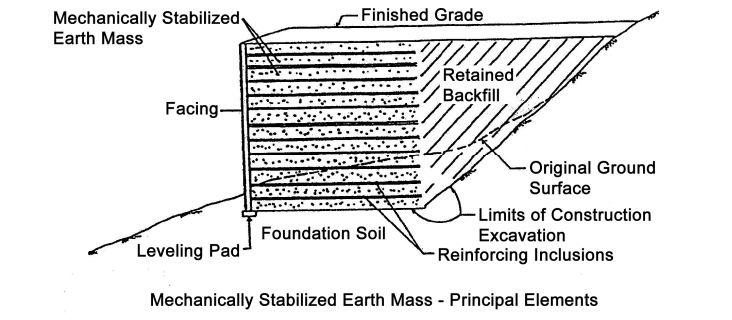
7. Mechanically Stabilized Earth (MSE) Walls:
MSE walls consist of precast concrete or steel facing panels connected to soil or geosynthetic reinforcement layers. The reinforcement layers, typically made of geotextiles or geogrids, provide additional tensile strength to the soil mass, improving stability. MSE walls are widely used in highway and railway embankments, bridge abutments, and other large-scale retaining applications.
Mechanically Stabilized Earth (MSE) walls, also known as reinforced soil walls, are structures that combine reinforcing elements with compacted soil to create a stable retaining wall system. MSE walls offer several advantages such as cost-effectiveness, ease of construction, and flexibility.
Beta Design Consultants engineers have designed and specified MSE walls in many applications including:
- Retaining Walls: MSE walls are extensively used as retaining walls in various civil engineering projects. They are employed to stabilize soil and prevent slope failures, providing support for embankments, highways, railways, and other infrastructure. MSE walls can accommodate a wide range of wall heights and configurations, making them suitable for both small-scale and large-scale projects.
- Bridge Abutments: MSE walls are often utilized as bridge abutments, providing support and stability for the approach embankments. They can withstand heavy loads and accommodate differential settlements effectively. MSE walls are a preferred choice due to their ease of construction, cost-effectiveness, and ability to accommodate various foundation conditions.
- Cut and Fill Slope Stabilization: MSE walls are employed to stabilize cut and fill slopes in highway and railway projects. By providing reinforcement to the soil, they prevent soil erosion, slope failure, and the need for excessive earthwork. MSE walls allow for steeper slope angles while maintaining stability and safety.
- Noise Barriers: MSE walls can serve as effective noise barriers alongside highways, railways, or industrial areas. The reinforced soil structure provides the necessary sound insulation, reducing noise pollution in surrounding areas. MSE walls can be designed to incorporate sound-absorbing materials for enhanced noise reduction.
- Embankment Reinforcement: MSE walls are used to reinforce and stabilize embankments, particularly in areas with soft or weak soils. The combination of reinforcement layers and compacted soil provides strength and stability to the embankment, minimizing settlement and potential failure.
- Coastal Erosion Control: MSE walls are employed for coastal erosion control and shoreline stabilization. They help prevent coastal erosion by providing a stable and durable structure that resists wave action and protects the shoreline. The flexibility and permeability of MSE walls allow for natural drainage and vegetation growth, contributing to ecological sustainability.
- Landscaping and Aesthetics: MSE walls can be utilized for landscaping purposes, creating terraced gardens, seating areas, or decorative structures. The facing elements of MSE walls can be customized to enhance the visual appeal and integrate with the surrounding environment.
The versatility and adaptability of MSE walls make them suitable for a wide range of applications. Our consulting Geotechnical and Structural Engineers expertise would undertake proper design, considering factors such as soil conditions, loads, and hydraulic forces, to ensure the stability and performance of MSE walls in specific project requirements. Our geotechnical and structural engineers would ensure the walls meet the desired functionality and safety standards.
8. Anchored Walls (embedded walls)
Anchored walls combine the use of a facing system (such as gravity or MSE walls) with the inclusion of tensioned anchors or tiebacks. The anchors extend into the soil behind the wall and are secured to provide additional lateral resistance. Anchored walls are suitable for high retaining heights and challenging soil conditions. For more information, please refer to our Ground Anchors and Soil Nails.
These are just a few examples of earth retaining structures commonly designed and assessed by our teams in engineering practice. The selection of the appropriate type depends on factors such as the height of the retaining wall, soil conditions, available space, construction method, and project requirements. Each type of structure has its advantages and limitations, and a thorough analysis of site-specific conditions is necessary to determine the most suitable solution.
The design of the earth retaining structure does not only require structural engineering input, but also require geotechnical engineering support.
Our team of geotechnical engineers provides the following services:
- Site Investigation: Beta Geotechnical Engineers conduct thorough site investigations to assess soil properties, groundwater conditions, and geological factors that can affect the design of earth retaining structures. This involves collecting soil samples, performing in-situ testing, and analysing data to determine soil strength, stability, and bearing capacity.
- Slope Stability Analysis: Beta Geotechnical engineers evaluate the stability of natural or man-made slopes to ensure the safety and integrity of earth retaining structures. They analyse factors such as soil properties, slope geometry, groundwater conditions, and external loads to assess the potential for slope failures and recommend appropriate slope reinforcement measures.
- Retaining Wall Design: Beta Geotechnical Engineers play a crucial role in designing various types of retaining walls, such as gravity walls, cantilever walls, anchored walls, and mechanically stabilized earth (MSE) walls. They consider factors like soil properties, retained material characteristics, surcharge loads, water pressure, and seismic forces to determine the most suitable design parameters and construction methods.
- Earth Pressure Analysis: Beta Geotechnical Engineers analyse the lateral pressures exerted by soil against retaining walls or structures. They consider factors such as soil properties, wall geometry, groundwater conditions, and construction sequencing to calculate earth pressure distribution and ensure that the design can withstand the anticipated loads.
- Soil Reinforcement Design: In cases where additional strength or stability is required, geotechnical engineers design soil reinforcement systems for earth retaining structures. This may involve incorporating geosynthetic materials, such as geotextiles, geogrids, or geocells, into the soil mass to enhance its strength, improve stability, and reduce deformation.
by Beta Geotechnical Engineers
After our Geotechnical Engineers undertake their studies, they work with our Structural Engineers to study soil-structure interaction. Our Structural Engineers provide the following services related to the structural design of earth retaining structures:
- Structural Analysis: Beta Structural Engineers analyse the structural behaviour of earth retaining systems, ensuring they can withstand the applied loads and resist external forces. They consider factors like material properties, geometry, boundary conditions, and construction sequencing to model and analyse the structural response, verifying the safety and stability of the retaining structure.
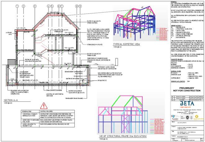
- Retaining Wall Design: Beta Structural Engineers are responsible for designing the structural components of retaining walls, such as wall footings, stem walls, toe slabs, and coping beams. They consider factors like load distribution, reinforcement detailing, durability, and constructability to develop robust and cost-effective designs.
- Construction Detailing: Beta Structural Engineers provide detailed construction drawings and specifications, including reinforcement layouts, concrete grades, wall thicknesses, and connection details. These drawings ensure proper execution of the design and facilitate communication between the design team and contractors during construction.
- Seismic Design: Earth retaining structures must be designed to withstand seismic forces if these are applicable. Our Structural Engineers consider the local seismic hazard, soil-structure interaction, and dynamic response of the structure to develop appropriate seismic design criteria. This may involve incorporating additional reinforcement, designing for ductility, and considering specific detailing requirements to enhance the structure's resilience.
- Construction Monitoring and Quality Assurance: Beta Structural Engineers may be involved in construction monitoring and quality assurance to ensure that the retaining structure is built according to the design specifications. They perform site inspections, review construction materials, and conduct tests to verify the structural integrity and compliance with design standards.
In summary, our team of Geotechnical and Structural Engineers collaborate closely to design earth retaining structures. Geotechnical engineers provide essential services related to site investigation, slope stability analysis, earth pressure analysis, and soil reinforcement design. Structural engineers, on the other hand, are responsible for structural analysis, retaining wall design, construction detailing, seismic design, and construction monitoring. By working together, our mutli-discipline teams ensure the safe and efficient design and construction of earth retaining structures.
Related projects
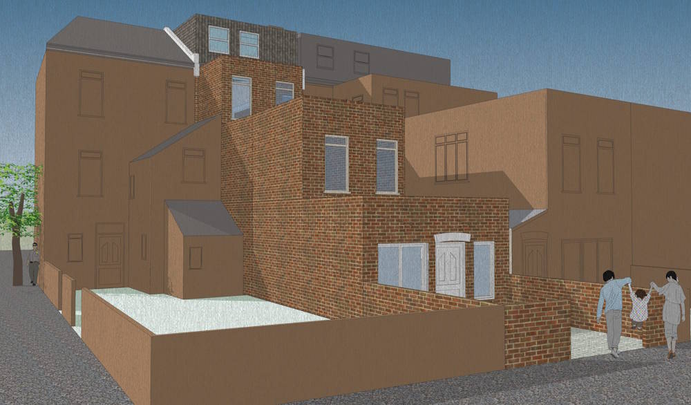
Planning Permission for 21 Boston Road Townhouse Conversion
Read More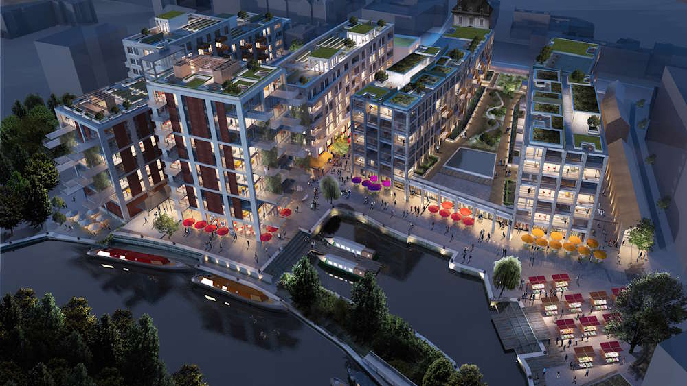
Brentford Waterfront Block B and C Temporary Works Design
Read More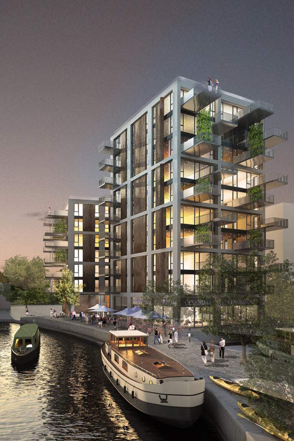
Brentford Waterfront Block K Temporary Works Design
Read More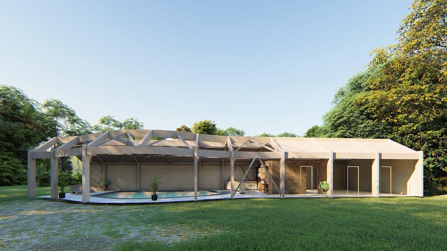
Leisure Swimming Pool House Design
Read More
Engine Yard Punching Shear Slab Strengthening
Read More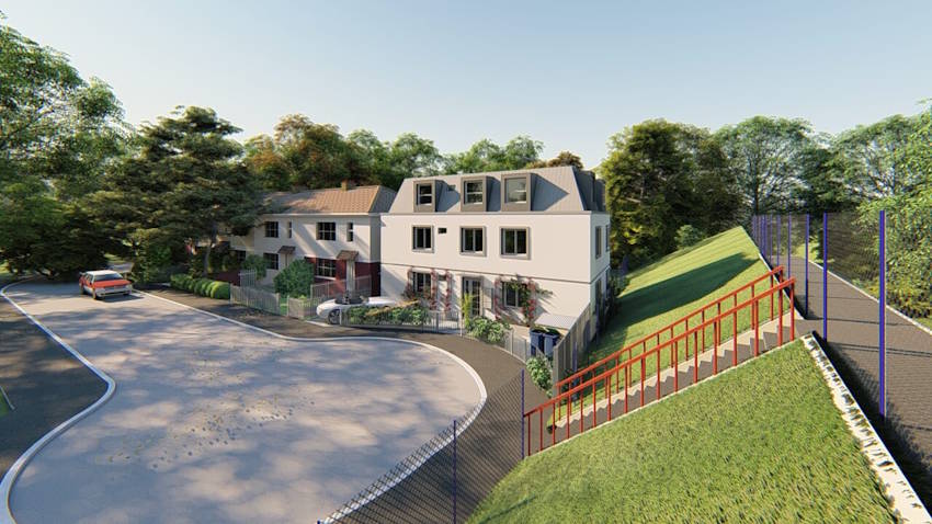
Planning Application for Three Story Residential Building
Read More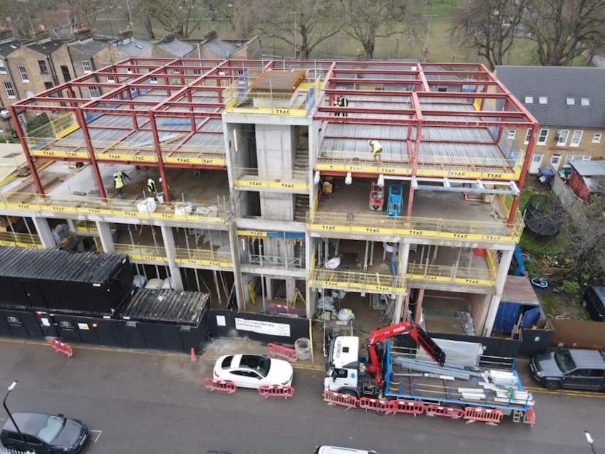
Helmsley Place-Steel Connections Design and Detailing
Read More
Planning Permission for a Basement in a Conservation Area
Read More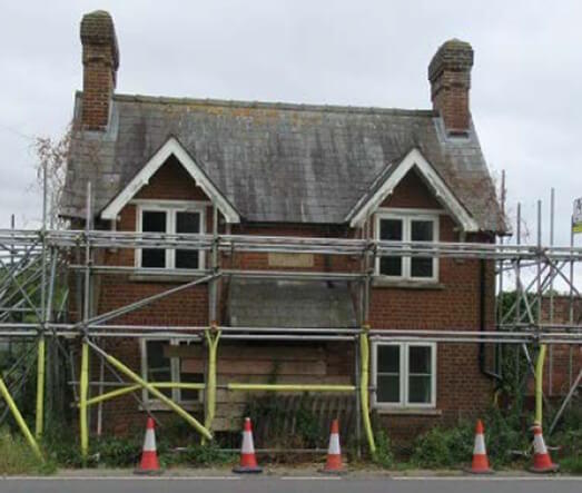
Structural Repairs of a Listed Building
Read More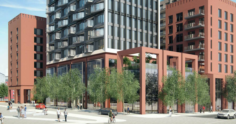
One West Point – Design of Support System for Cladding
Read More
Orchard House – RC Column Strengthening using CFRP
Read More
Structural Design of 3 Storey Building
Read More
Queens Rise- Steel Structure Connection Design and Detailing
Read More
St Peter’s Hospital Staff Accommodation, Piled Rafts Design
Read More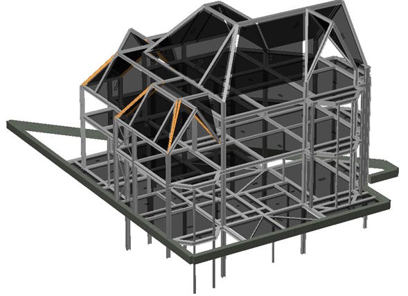
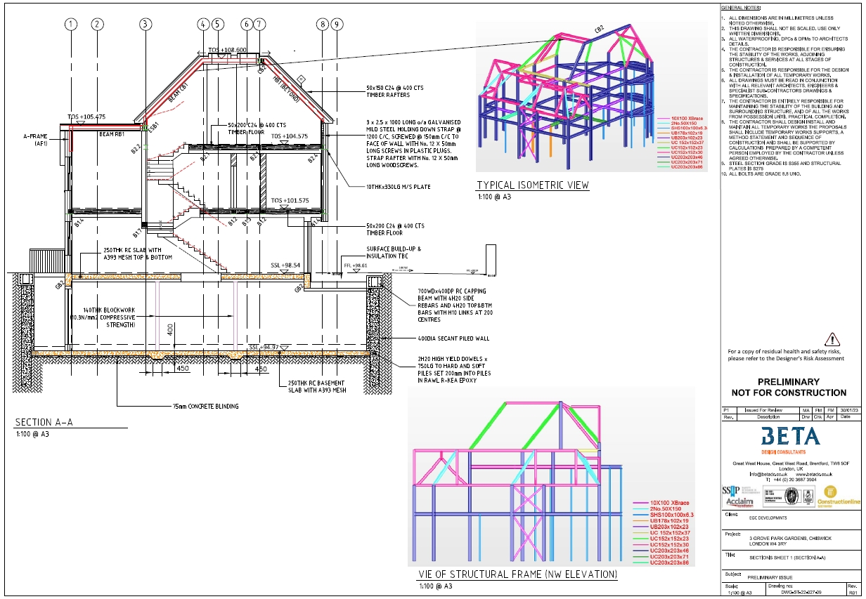
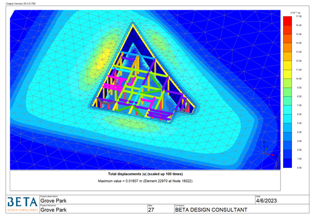
Grove Park Gardens 4 Storey Residential Development
Read More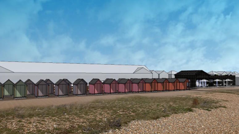
Coast Drive Visitor Centre, Watersport and Beach Huts
Read More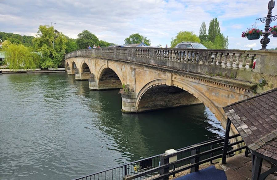
Structural Assessment of Henley Masonry Arch Bridge
Read More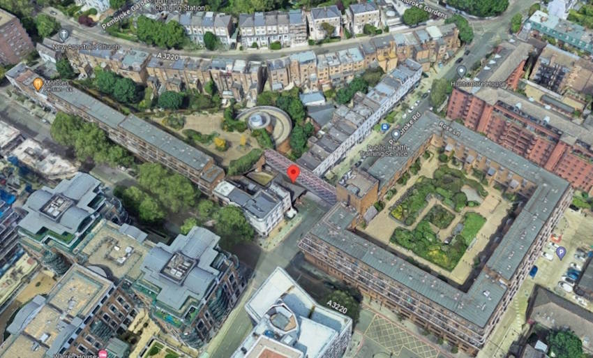
Pembroke Road Footbridge - Structural Investigation & Strengthening
Read More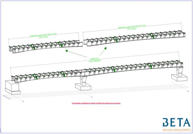
Concept Design of Sedhiou Bridge and Roads Network
Read More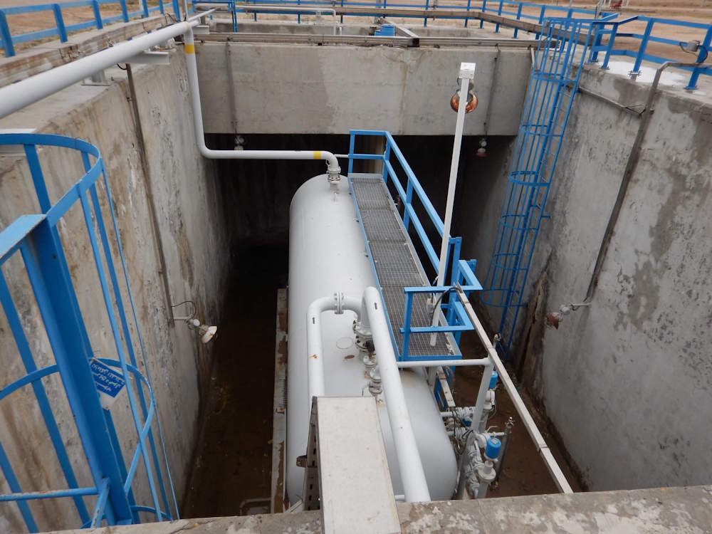
BP Deep Water Sump Assessment and Concrete Repair Design
Read More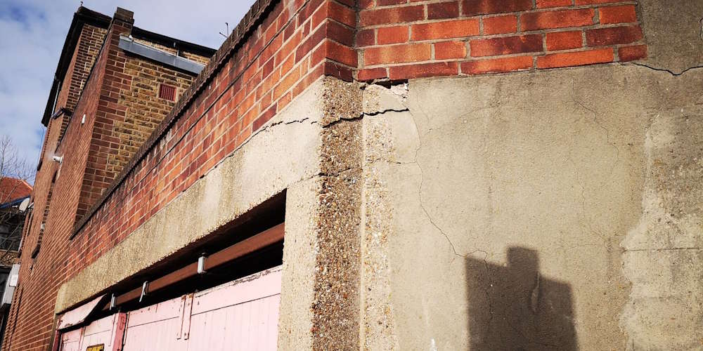
Fulham Palace Road Temporary Works Design
Read More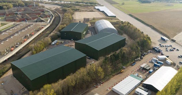
Stage 50 Bovingdon Airfield Studios
Read More
Concept Design of Cité Administrative Koloma
Read More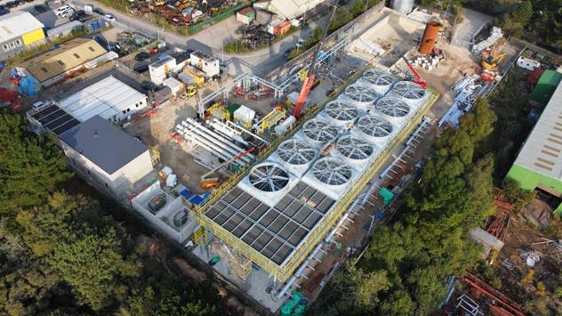
United Downs Deep Geothermal Power Plant
Read More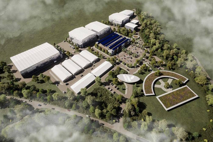
Stage 50 Wycombe Film Studios Village
Read More