Bus Depot Electrification Harrow
Bus Depot Electrification
Bus Depot Electrification – TFL Harrow Bus Depot Civil and Structural Design Services
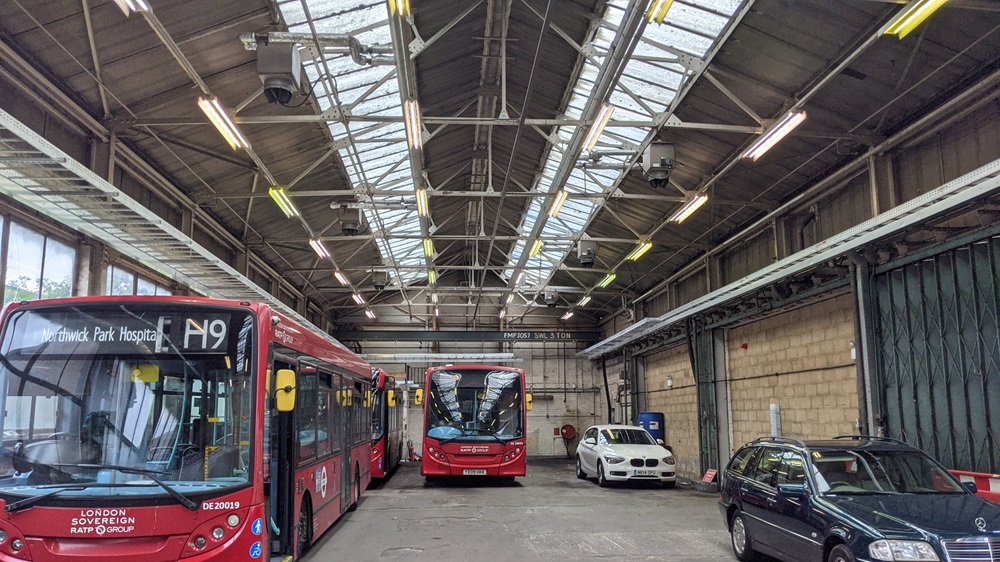
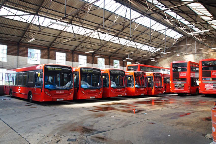
Transport for London TFL is embarking on a programme to install electric charging infrastructure to the bus network. This is rolled out to chosen bus depots and Harrow bus depot (Harrow Weald) is one of them. The main depot, built in 1900 and the depot extension built in 1960 as well as the ex-Hearn Coaches depot built in 1947, were all going to be adapted to receive this infrastructure of charges, electrical equipment and containment cables.

Beta Design Consultants were commissioned by the Client, an electrification contractor working for RATP/TFL, to carry out the following services:
- Inspection of existing TFL bus depot structures built at different stages from 1900 to 1980 and assessing the roof, walls and foundations ability to accommodate new loads.
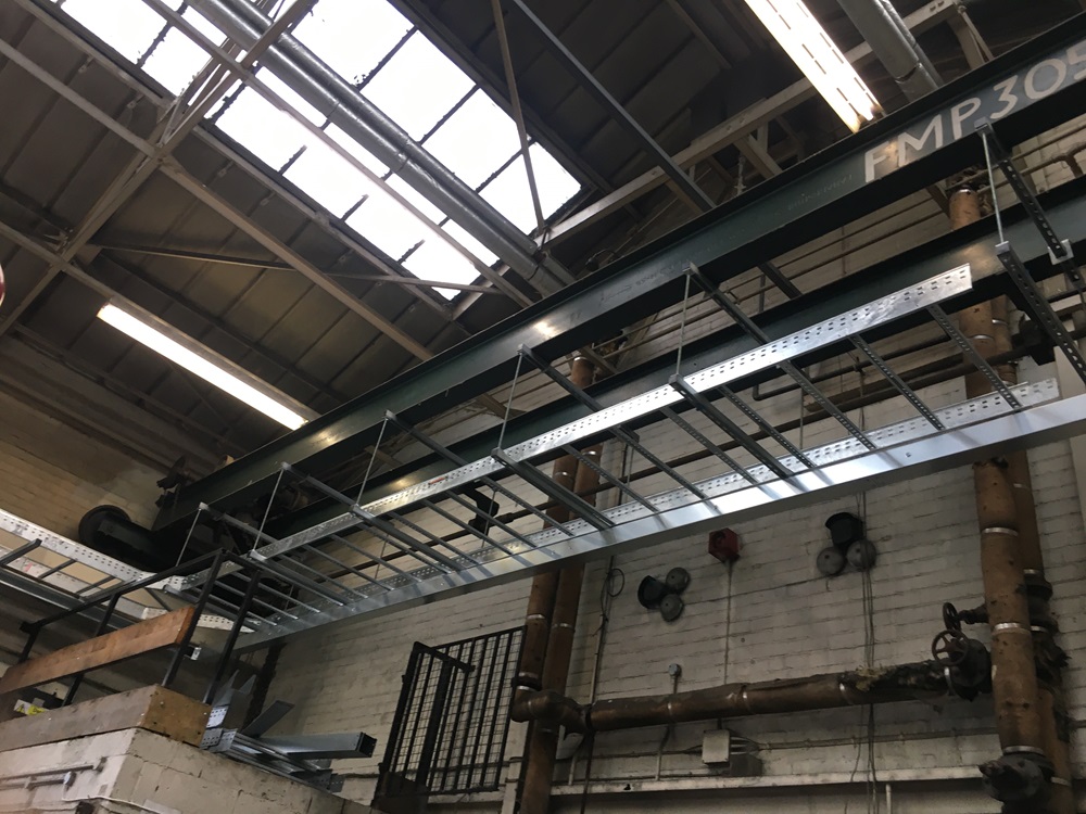
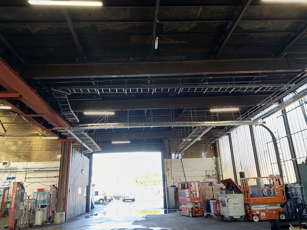
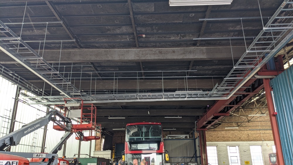
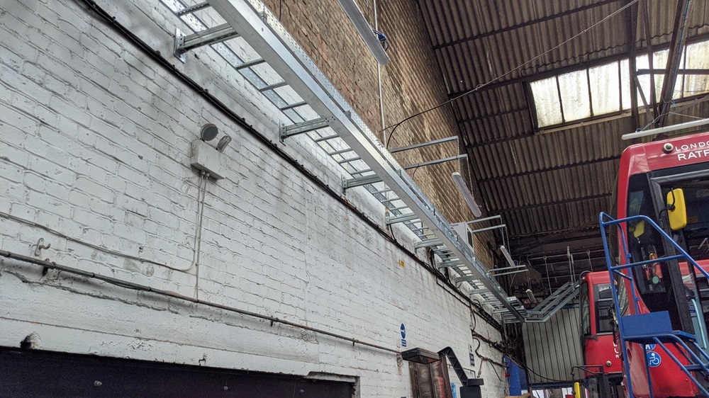
- Design of supports for new cable containment racks/ladders needed to electrify the bus network.
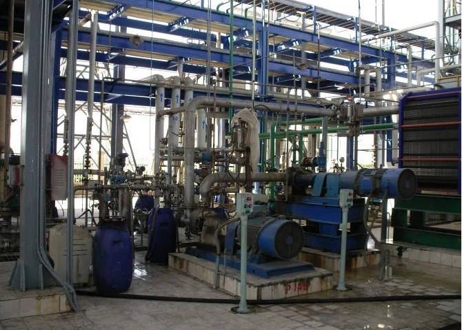
- Design of new equipment foundations, including transformer, feeder pillar and other electrical equipment (e.g. RMU, GPR enclosures).
- Arranging trial pits and assessment of impact of new equipment foundations on existing depot foundations.
- Assessment of cracking in existing masonry depots.
Beta Solution
We carried out a measured survey to establish the layout and sections sizes of the depot structure. This allowed us to establish its load carrying capacity following a structural analysis. The impact of adding new cable containment supports to the roof truss, super structure beams and super structure columns was then established. Supports for the containment, using a mix of unistructs and bespoke structural supports then followed. Spacing of supports varied from at 3m spacing horizontally and vertically to supports at and before/after every bend/radius.
One of the challenges was to introduce new masonry supports in walls that had some historic cracking. The solution was to divert the containment cables away from locations of worst cracking to avoid loading an already stressed wall.
Related projects
BP GF Gas Plant Asset Integrity and Refurbishment
Read More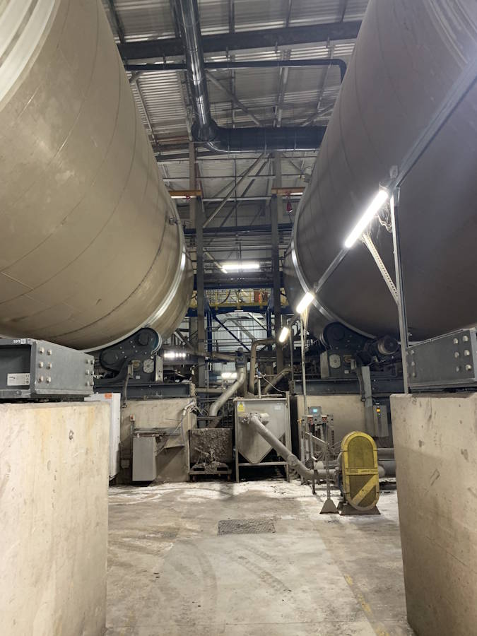
Energy from Waste Plant - Process Water Drainage Design
Read More
Concept Design of Cité Administrative Koloma
Read More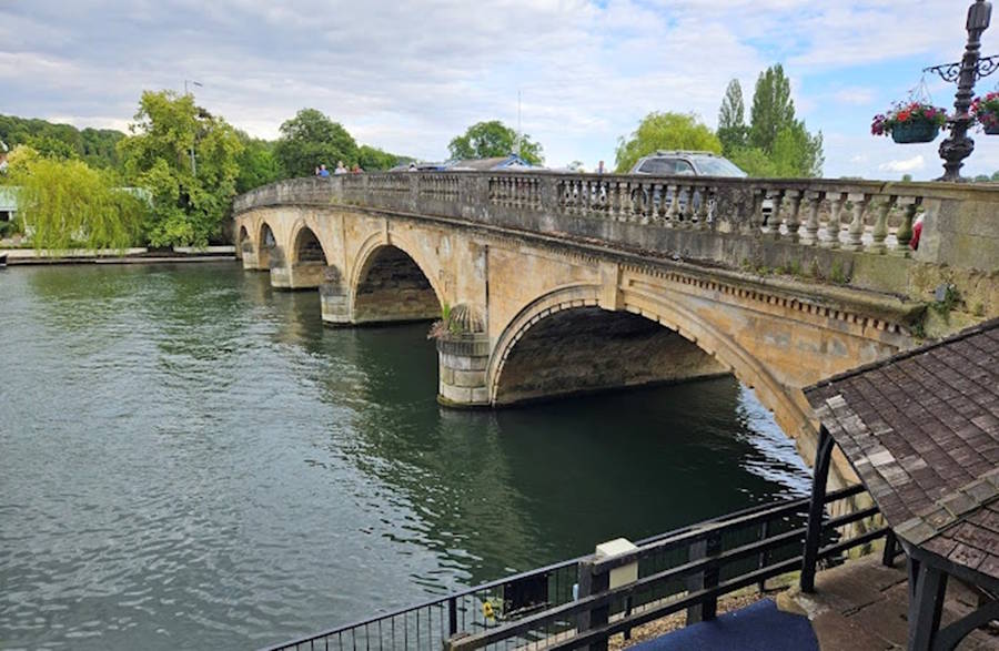
Structural Assessment of Henley Masonry Arch Bridge
Read More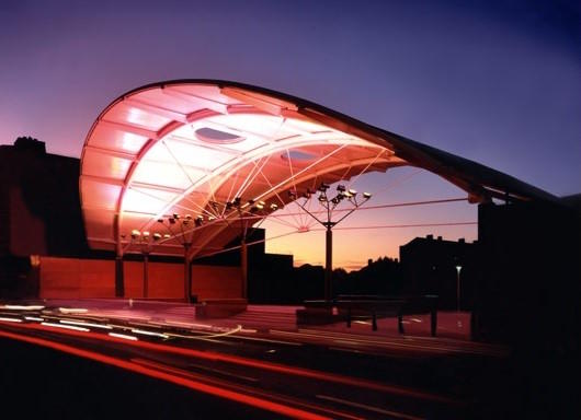
Peckham Arch Condition Survey & Life Extension Consulting Services
Read More
Pembroke Road Footbridge - Structural Investigation & Strengthening
Read More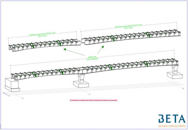
Concept Design of Sedhiou Bridge and Roads Network
Read More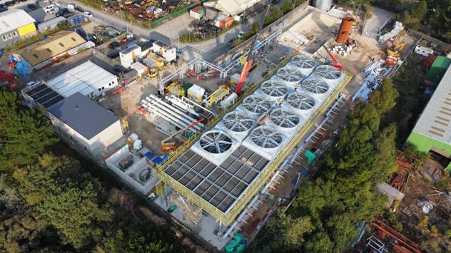
United Downs Deep Geothermal Power Plant
Read More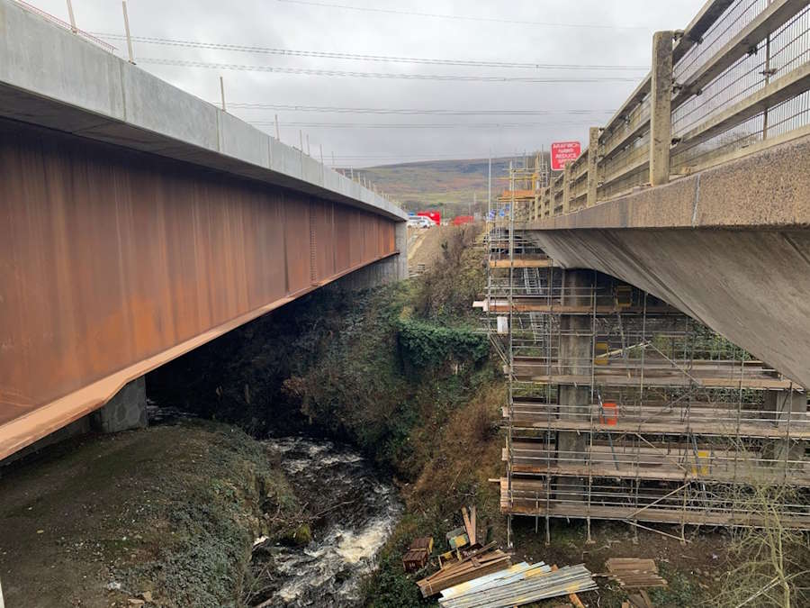
Nant Melyn Bridge Inspection for Assessment
Read More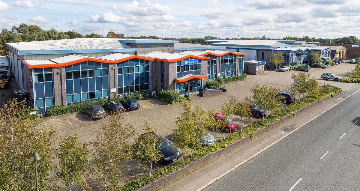
Action Court Warehouse Extension
Read More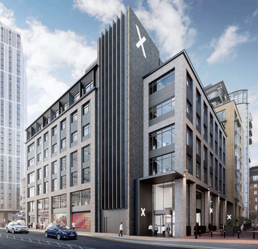
CFRP and HPC Concrete Strengthening for Brindleyplace
Read More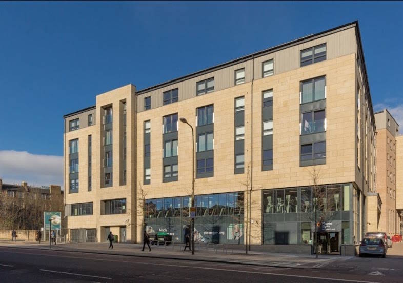
Engine Yard Punching Shear Slab Strengthening
Read More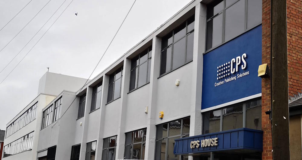
CPS House Jacketing to Strengthen RC Beams
Read More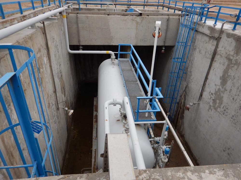
BP Deep Water Sump Assessment and Concrete Repair Design
Read More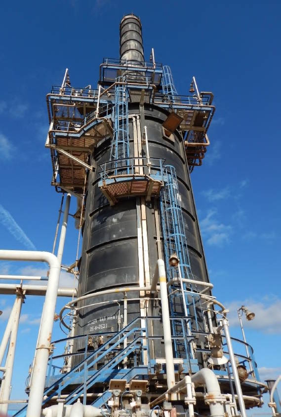
BP Heater Foundation Concrete Repair
Read More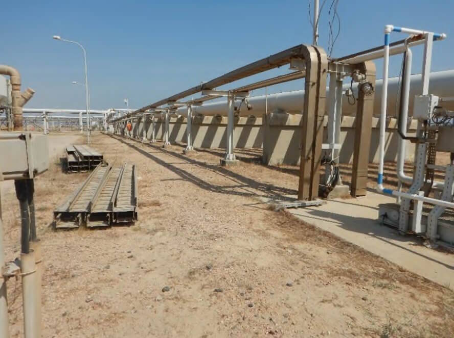
BP GF Gas Plant – Slug Catcher Foundation Walls RC Repair
Read More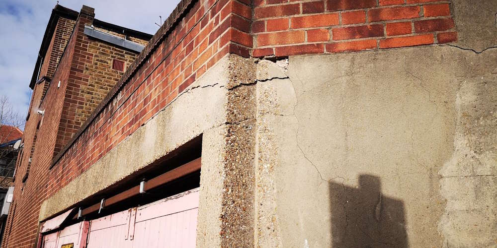
Fulham Palace Road Temporary Works Design
Read More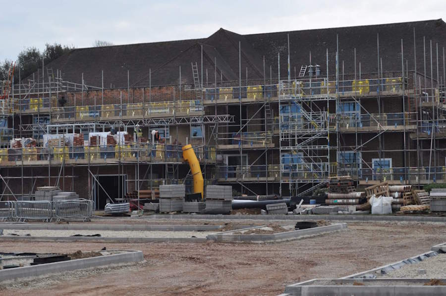
Harwell Campus-Concrete Strengthening
Read More
Kennedy Institute Extension - Flat Slab Punching Shear Strengthening
Read More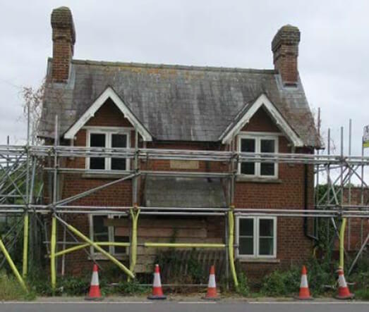
Structural Repairs of a Listed Building
Read More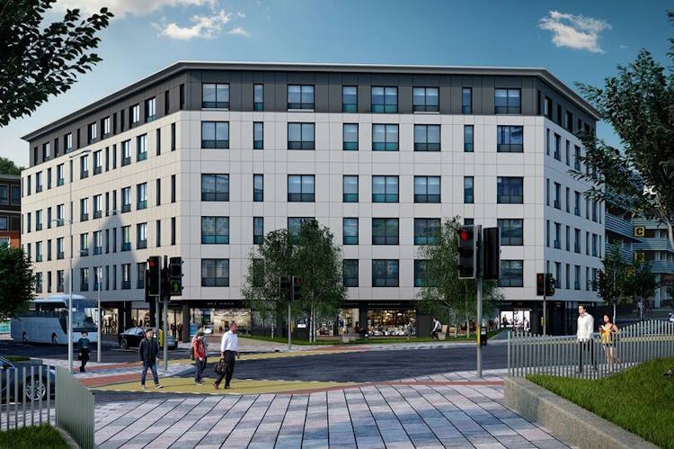
Orchard House – RC Column Strengthening using CFRP
Read More
Stanmore House Strengthening
Read More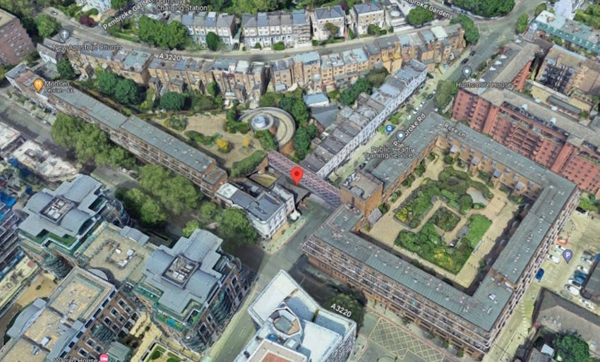
Northside Garages Structural Investigation
Read More
RAAC Investigation and Structural Strengthening
Read More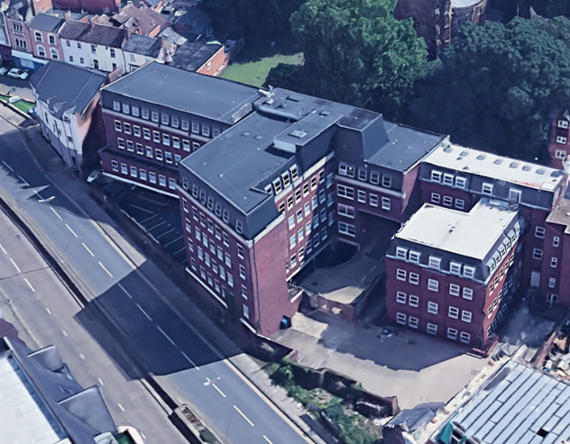
Spire Academy (Horizon Academy) Car Park Refurbishment
Read More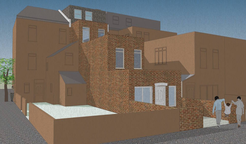
Planning Permission for 21 Boston Road Townhouse Conversion
Read More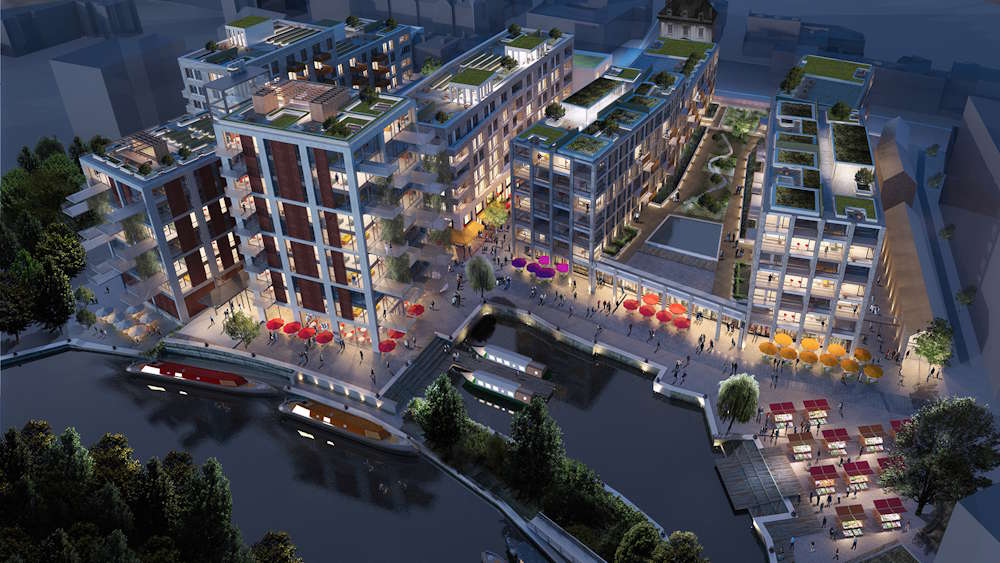
Brentford Waterfront Block B and C Temporary Works Design
Read More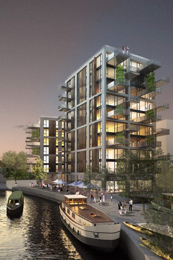
Brentford Waterfront Block K Temporary Works Design
Read More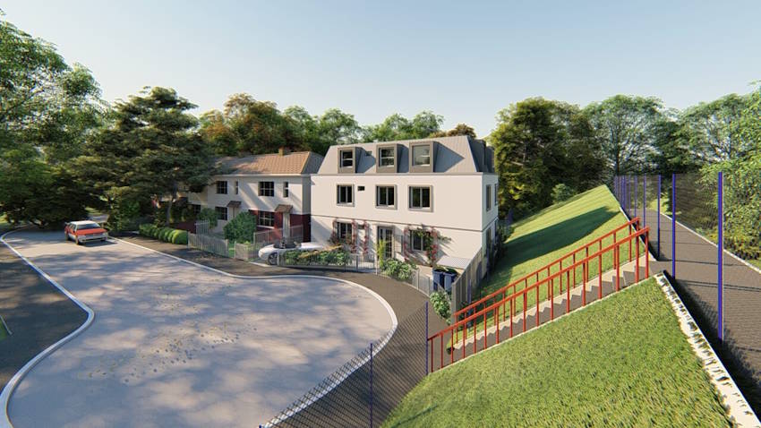
Planning Application for Three Story Residential Building
Read More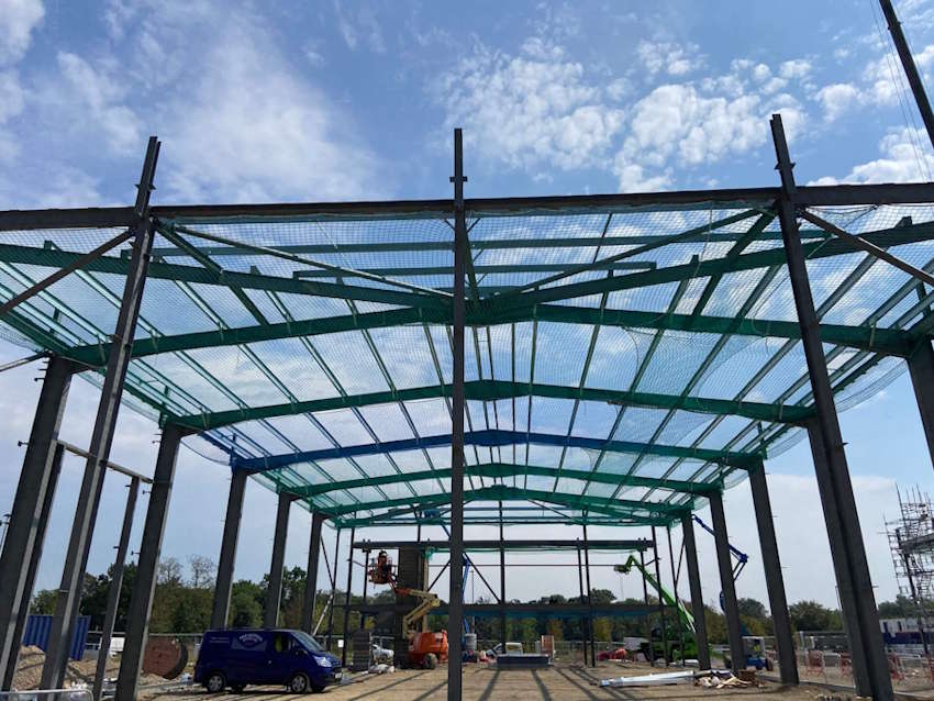
Value Engineering for Warehouse and Office Building
Read More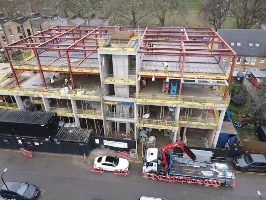
Helmsley Place-Steel Connections Design and Detailing
Read More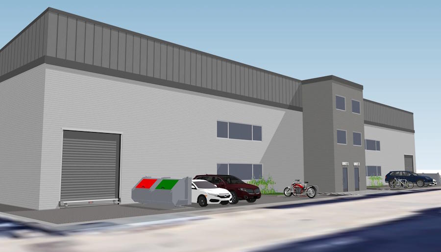
Planning Permission for New Warehouse, Ealing
Read More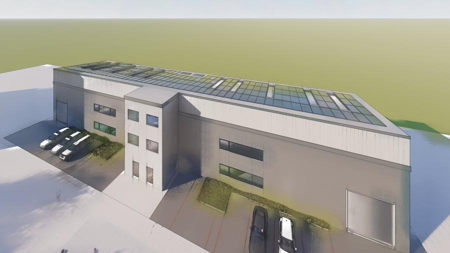
Three Story Warehouse Steel Structure Design
Read More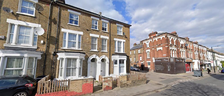
Planning Permission for a Basement in a Conservation Area
Read More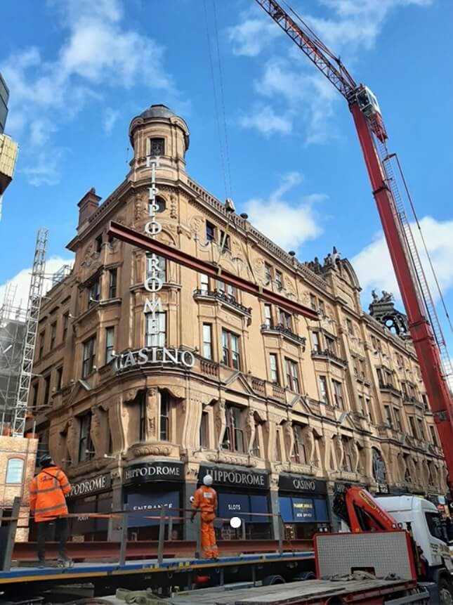
London Hippodrome Roof Extension – Structural Design and Detailing
Read More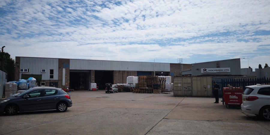
Polybags Ltd Warehouse Extension in Lyon Way
Read More
One West Point – Design of Support System for Cladding
Read More
Structural Design of 3 Storey Building
Read More
Queens Rise- Steel Structure Connection Design and Detailing
Read More
Grove Park Gardens 4 Storey Residential Development
Read More