Mount View Road Bridge – Structural Strengthening and Remedial Works
Project Summary
Project: Mount View Road Bridge – Structural Strengthening and Remedial Works
Client: Project Centre
Location: Mount View Road, Islington, London, N4 4SE
Structural Engineer: Beta Design Consultants
Sector: Infrastructure & Transport
Material: Masonry
Expertise: Surveys and Investigation, NDT, Repairs and Strengthening
Services Provided
-
Structural Strengthening and Remedial Design
-
Masonry Crack Stitching and Repair Details
-
Ground Anchor and Spandrel Wall Restraint Design
-
Temporary Propping and Foundation Design
-
Access Scaffold Design
-
Coordination of Site Investigations and Construction Requirements
1. Project Overview
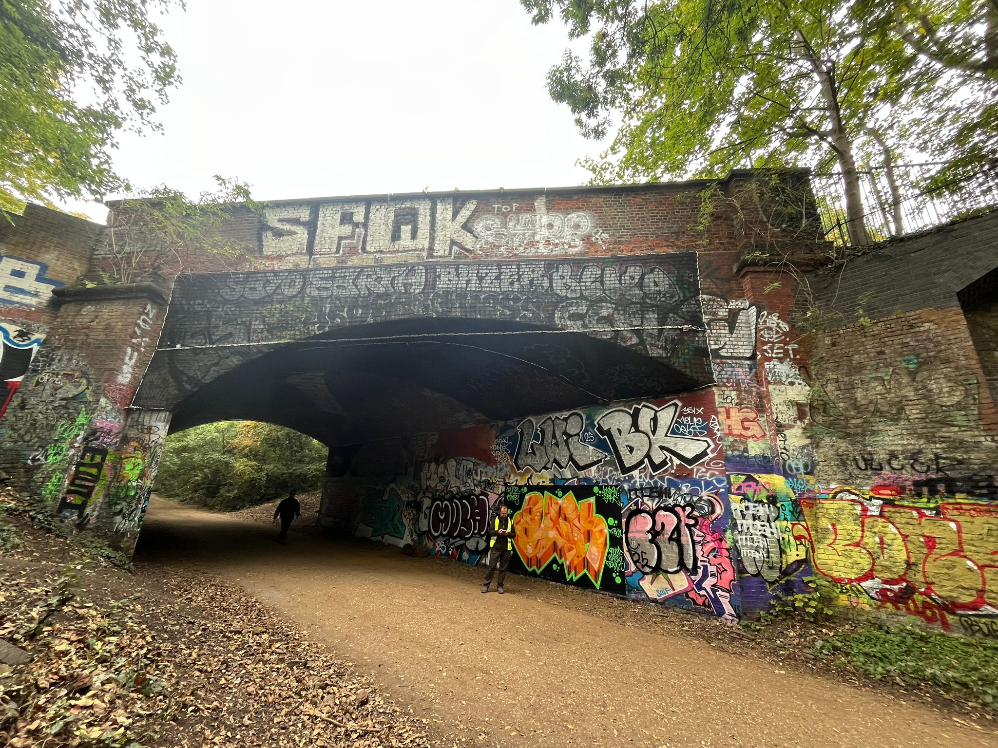
Beta Design Consultants (BDC) provided structural engineering design services for the strengthening and remedial works to the existing masonry arch bridge at Mount View Road, Islington, London.
The project involved developing a coordinated strengthening strategy to address cracking, mortar deterioration and localised masonry defects, while improving the restraint provided to the existing spandrel walls.
The bridge is a skew masonry arch, with an approximate skew angle of 38°. Its geometry, existing construction, buried utilities and restricted working space presented several engineering and construction challenges. The proposed works also required careful consideration of temporary structural support to maintain stability throughout the strengthening operations.
BDC's scope included permanent structural strengthening, masonry repair details, ground anchor design, temporary propping arrangements, temporary foundation details and access scaffold drawings.
The project demonstrates BDC's experience in the assessment and strengthening design of existing masonry infrastructure, particularly where permanent structural interventions must be coordinated with temporary works and constrained site conditions.
2. Technical Background: Understanding Masonry Arch Bridges
Masonry arch bridges are an important part of the UK's historic transport infrastructure. Many were constructed during the industrial revolution to facilitate the movement of goods and people, and continue to serve as part of the modern highway network.
Understanding their structural behaviour requires an appreciation of their original construction, geometry and load-transfer mechanisms.
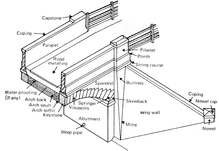
Unlike modern reinforced concrete or steel bridges, masonry arches primarily rely on compression to transfer loads. The interaction between the arch ring, backing material, fill, spandrel walls and abutments is fundamental to their structural performance.
A typical masonry arch bridge comprises several interconnected structural elements:
-
Arch ring: The principal load-bearing component, transferring loads through compression towards the abutments.
-
Spandrel walls: Retaining walls alongside the arch barrel that contain the fill and contribute to the overall stability of the bridge.
-
Backing and fill: Material above and behind the arch ring that distributes applied loads and influences the structural response.
-
Abutments: Provide the horizontal and vertical restraint required to resist the arch thrust.
-
Foundations: Transfer the resulting forces safely into the supporting ground.
The structural assessment of a masonry arch requires consideration of the position of the thrust line within the arch ring. The masonry has limited tensile capacity, and the development of excessive eccentricity, cracking or hinge mechanisms can compromise structural stability.
The traditional concept of the inverted hanging chain provides a useful illustration of arch behaviour: an arch shape can be related to the form of a hanging chain under corresponding loading conditions.
However, actual masonry arch behaviour is influenced by the geometry, material properties, fill depth, loading arrangement, boundary conditions and interaction between the different structural components.
For this reason, bridge inspections and structural assessments must consider the bridge as an integrated structural system rather than assessing the arch ring in isolation.
3. Bridge Condition Inspection – Identifying Structural Defects
Condition inspections are essential for identifying defects that may affect the structural performance and long-term durability of masonry arch bridges.
General Inspections (GI), Principal Inspections (PI) and Inspections for Assessment (IA) provide different levels of information about the condition of the structure and the need for further investigation.
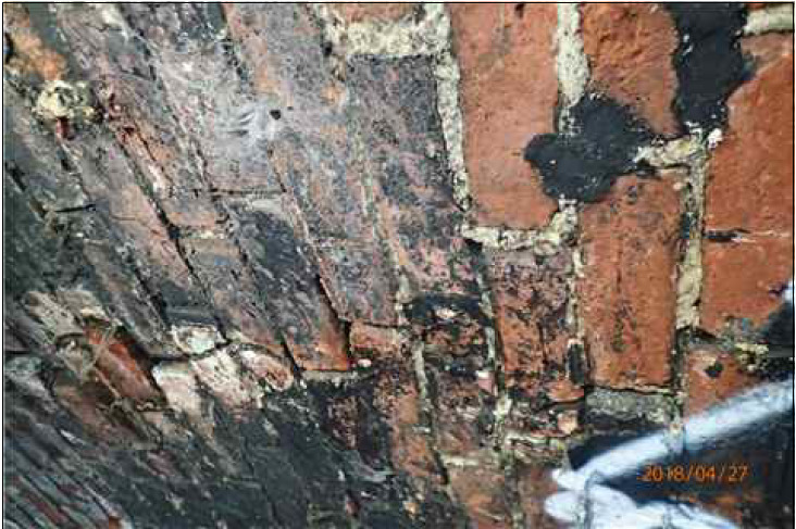
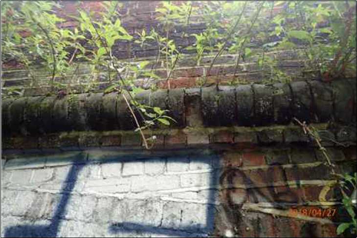
During bridge inspections, particular attention is given to cracking, separation, deterioration of mortar joints, water ingress and deformation of the masonry.
Typical defects include:
|
Defect |
Potential cause |
Structural significance |
|
Longitudinal cracking |
Spandrel wall separation, movement or spreading |
May indicate loss of restraint and instability of the outer masonry |
|
Ring separation |
Deterioration or failure of mortar between masonry rings |
Can compromise composite action between the arch rings |
|
Diagonal cracking |
Differential settlement or localised structural movement |
May indicate movement of the abutments or foundations |
|
Mortar loss |
Weathering, water ingress and deterioration |
Reduces masonry integrity and allows further water penetration |
|
Masonry spalling |
Weathering, frost action or localised damage |
Can reduce the effective masonry section |
|
Efflorescence and leaching |
Water penetration and movement of soluble salts |
May indicate drainage or waterproofing defects and potential long-term deterioration |
Condition Assessment at Mount View Road
The inspection information supplied for Mount View Road identified several areas requiring structural intervention.
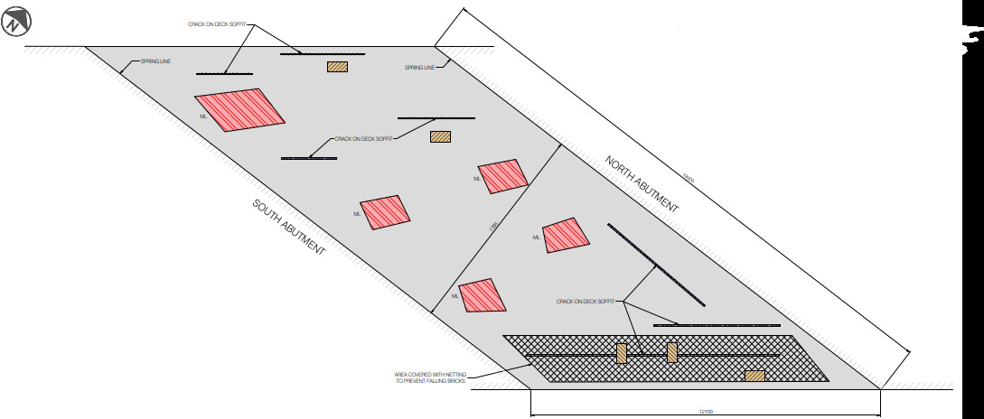
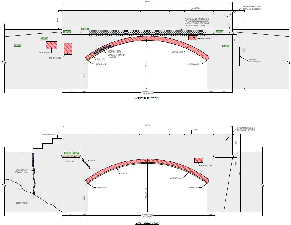
The defects were categorised on the strengthening drawings as follows:
-
Cracking (C1–C7): Cracks within the existing masonry requiring stitching and local strengthening.
-
Mortar loss (ML1–ML5): Areas of deteriorated or missing mortar requiring preparation and repointing.
-
Masonry spalling (S1–S5): Localised damage requiring removal and replacement of defective masonry units.
The defect locations were incorporated into the structural drawings to coordinate the proposed repair works with the wider strengthening strategy.
A particularly important consideration was the restraint of the existing spandrel walls. The strengthening scheme therefore incorporated grouted ground anchors connected to structural steel members to provide additional restraint.
4. Structural Assessment Methods and Bridge Modelling
The assessment of masonry arch bridges requires an appropriate understanding of their geometry, construction, material properties and loading conditions.
Depending on the complexity of the structure, different assessment methods can be adopted to establish its load-carrying capacity.
Level 1 – Empirical Assessment: MEXE Method
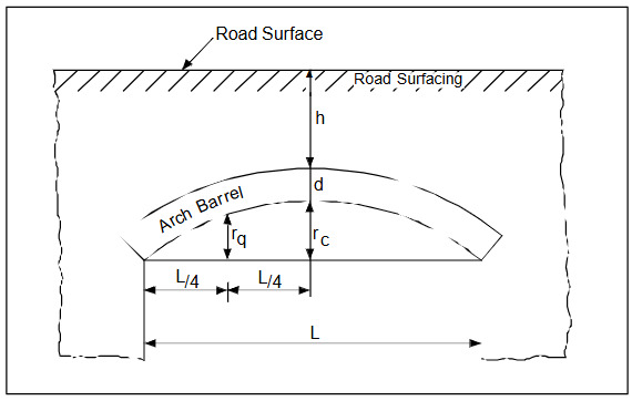
The Modified Military Engineering Experimental Establishment (MEXE) method is an established empirical approach used in the UK for preliminary assessment of masonry arch bridges.
It uses factors associated with the arch span, ring thickness, fill depth and other relevant characteristics to estimate the load-carrying capacity.
Although useful for screening and preliminary assessment, the method has limitations, particularly for structures with unusual geometry, significant deterioration or complex structural arrangements.
Level 2 – Limit Analysis and Mechanism Assessment
Limit analysis considers the possible formation of hinges within the arch ring and the development of a collapse mechanism.
The assessment investigates whether a stable thrust line can be established within the masonry under the applied loading conditions.
Specialist software, including Archie-M and Ring, can be used for this type of assessment, particularly for conventional masonry arches that satisfy the relevant modelling assumptions.
The method can be particularly effective for standard arch bridges, although skewed geometry, three-dimensional behaviour and complex interaction with the surrounding fill may require more advanced analysis.
Level 3 – Finite Element Analysis (FEA)
Finite Element Analysis provides a more detailed approach to assessing complex masonry arch structures.
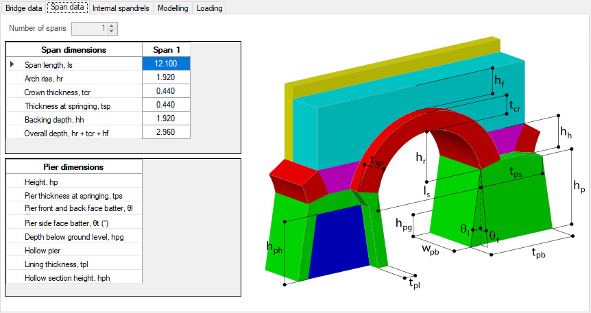
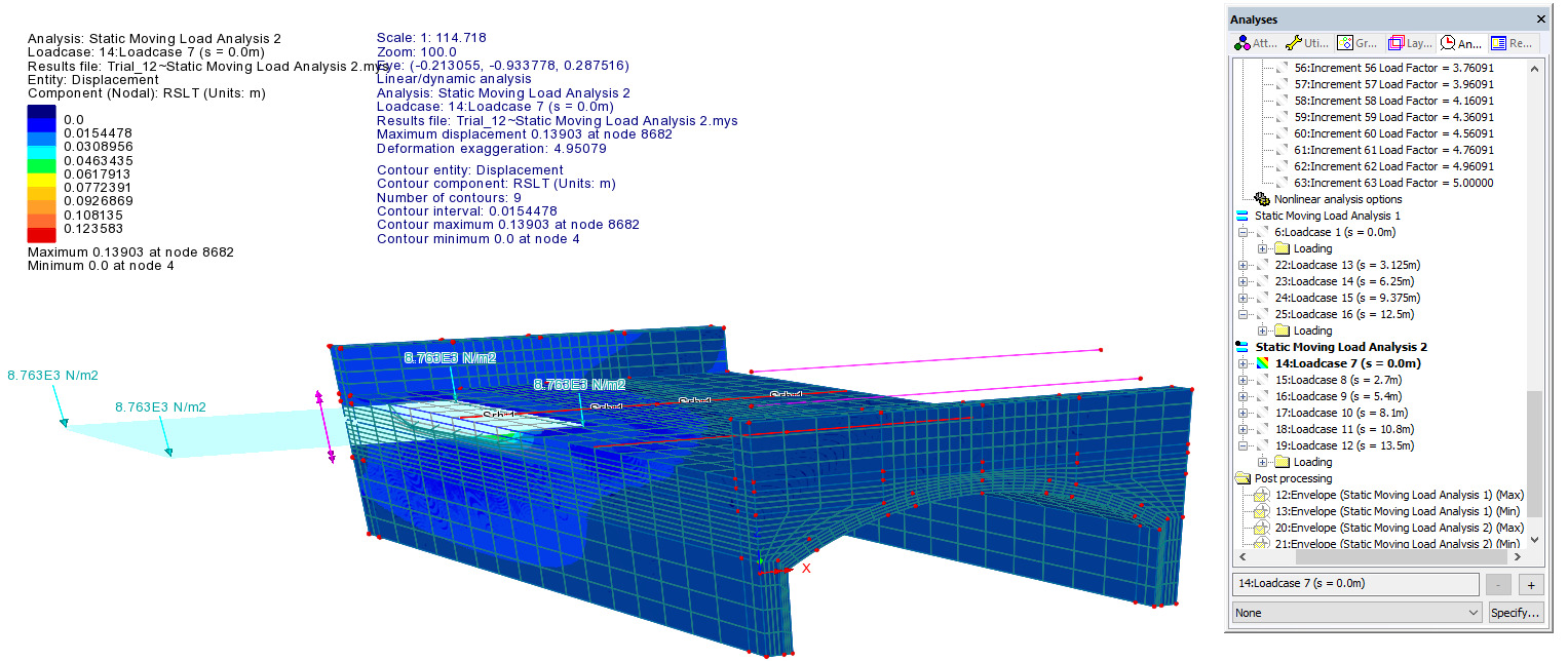
Three-dimensional modelling can be particularly useful where the bridge has significant skew, irregular geometry or complex interactions between the arch barrel, spandrel walls and surrounding ground.
Software such as LUSAS Bridges can be used to investigate structural behaviour, stress distribution and the interaction between different structural components.
The selection of the assessment methodology should reflect the complexity of the bridge and the quality of the available investigation information.
For Mount View Road, the documented design work addressed the strengthening requirements of the approximately 38° skew masonry arch and its associated structural components. The supplied project records do not establish which specific load-capacity assessment software or numerical modelling method was used.
5. Site Investigations and Non-Destructive Testing (NDT)
Reliable information about the existing construction is essential when designing strengthening interventions to historic masonry bridges.
Existing drawings do not always provide sufficient information about the arch profile, waterproofing, foundation arrangement or buried services.
Investigations may therefore be required to establish the actual construction and identify potential constraints before intrusive strengthening works commence.
Common investigation techniques include:
-
Ground Penetrating Radar (GPR): Used to investigate buried services, identify potential voids and obtain information about concealed construction.
-
Laser Scanning and LiDAR: Used to produce accurate three-dimensional representations of bridge geometry and identify potential deformation or movement.
-
Coring and material sampling: Used to investigate masonry and mortar properties where appropriate.
-
Trial holes: Used to establish the existing construction, waterproofing arrangement and location of buried services.
Trial Hole Investigations at Mount View Road
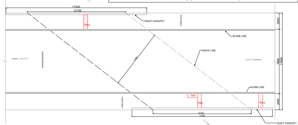
Four trial holes were undertaken by CBS Ltd to establish the existing construction beneath the footways and identify potential constraints affecting the proposed strengthening works.
The findings included:
|
Trial hole |
Location |
Investigation findings |
|
TH1 |
East footway |
Sound black waterproofing extending from the parapet base, encountered approximately 700 mm below finished ground level at the trench centre |
|
TH2 |
East footway |
Excavation to approximately 1.0 m near the parapet did not identify evidence of a bridge deck at the investigated location |
|
TH3 |
East footway |
Confirmed that the waterproofing followed the curved profile of the masonry arch rather than a flat deck arrangement |
|
TH4 |
West footway |
Waterproofing identified alongside a congested arrangement of buried services |
The west footway investigation identified several existing utilities, including gas pipes, clay drainage, communications ducts, HDPE ducts and cast-iron pipes at relatively shallow depths.
These findings were particularly important when developing the proposed ground anchor installation arrangements.
Further service detection, including CAT and GPR surveys, together with contractor verification, was identified as necessary before carrying out intrusive works.
6. Structural Strengthening and Masonry Repair Strategies
Masonry arch bridges can require a combination of structural strengthening and localised repairs depending on the nature and extent of the identified defects.
The selection of the appropriate intervention depends on the structural assessment, existing construction, condition of the masonry and practical constraints associated with installation.
Common strengthening and repair techniques include:
-
Crack stitching - Stainless steel or other suitable reinforcement bars can be installed within prepared masonry joints to provide continuity across cracked areas and improve local structural integrity.
-
Radial reinforcement and grouting - Radial pins and specialist grouting systems can be used where required to improve the integrity of masonry construction and provide additional local restraint.
-
Ground anchors and tie-backs - Grouted ground anchors or tie-back systems can provide additional restraint to spandrel walls and help control movement away from the arch barrel.
-
Arch strengthening - Depending on the assessment findings, strengthening may involve additional reinforcement, local reconstruction or other interventions to improve the structural performance of the arch.
-
Masonry repairs - Deteriorated mortar joints can be repointed, while defective or spalled masonry units can be removed and replaced with compatible materials.
6.1 Crack Stitching Using HeliBars
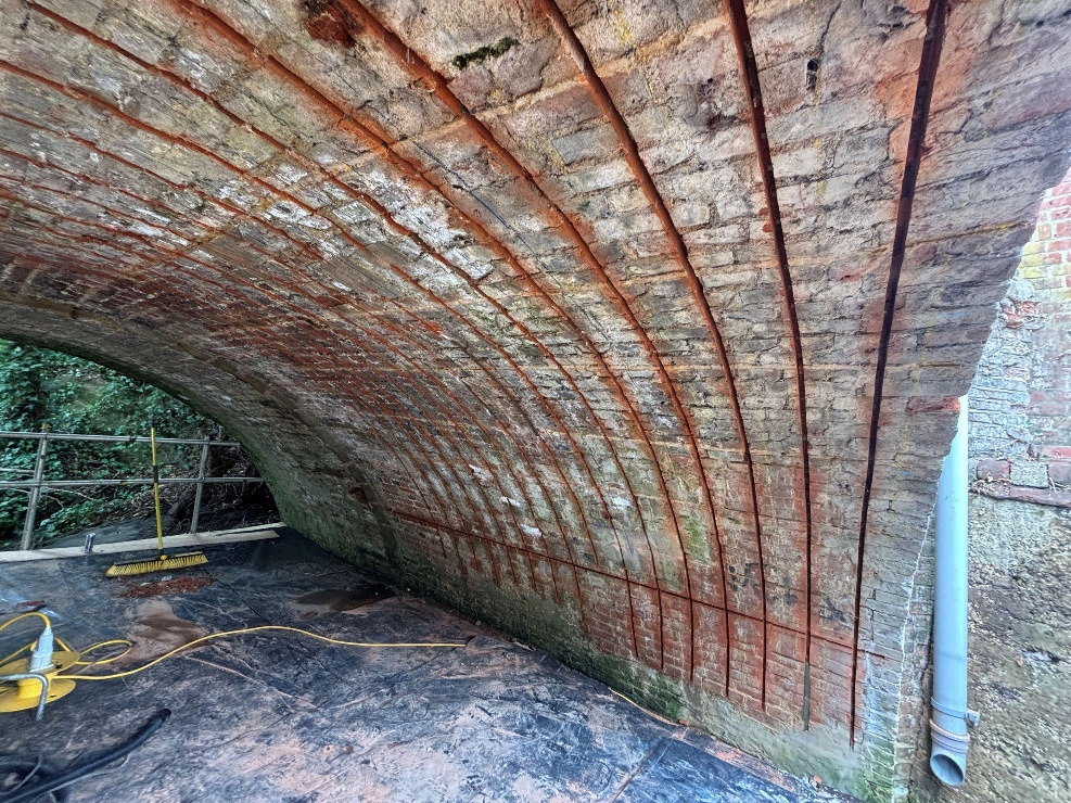
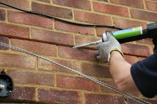
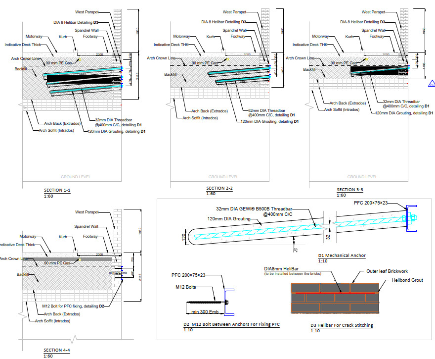
At Mount View Road, BDC developed a crack-stitching arrangement using 8 mm diameter HeliBars installed within prepared mortar joints and secured using HeliBond grout.
The longitudinal reinforcement was arranged at approximately six-course intervals, equivalent to approximately 450 mm vertically, subject to the existing masonry joint arrangement.
The specification also included a minimum 200 mm embedment into the embankment where indicated.
Additional reinforcement was detailed to the arch soffit, with HeliBars arranged at approximately 450 mm centres along the identified cracks.
Two vertical bars were also specified on either side of each crack, extending at least 500 mm beyond the crack or beyond the outermost cracks where applicable.
The installation specification included requirements for slot preparation, cleaning, dampening or priming where necessary, and filling with the specified grout.
Temperature restrictions were also specified to ensure appropriate installation conditions.
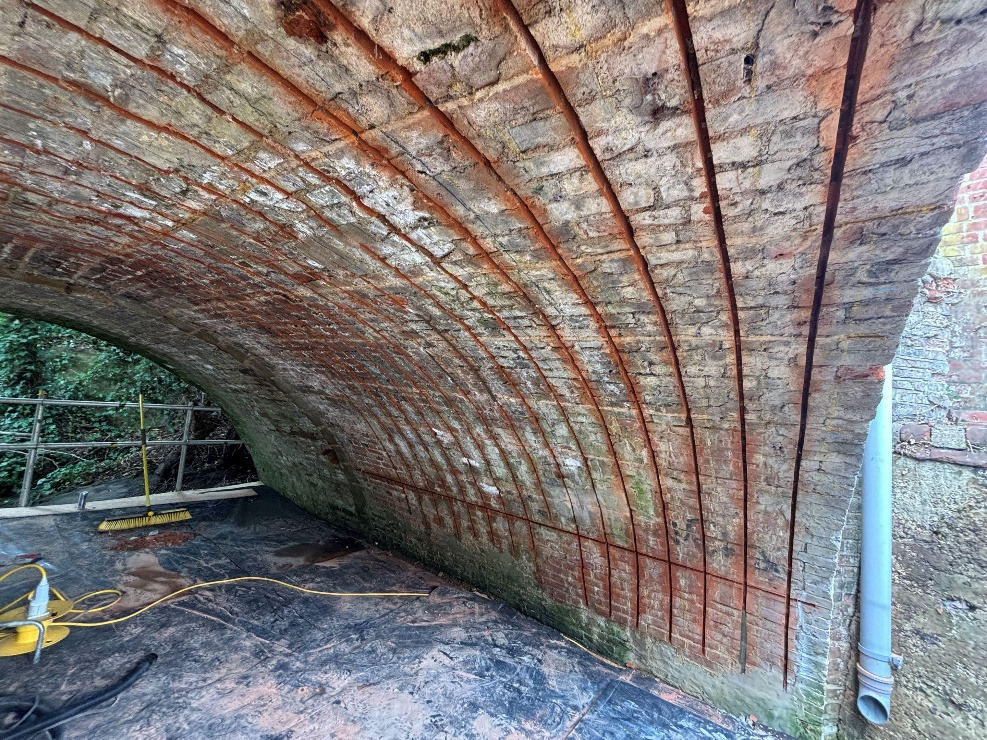
6.2 Radial Pins to the Arch Soffit
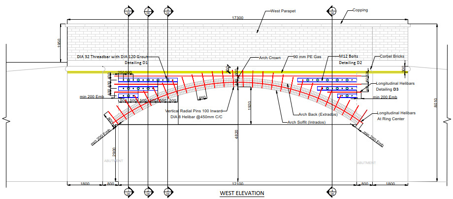
The strengthening drawings included 28 vertical radial pins installed from the soffit along the arch ring.
The pins were arranged at approximately 450 mm centres and positioned 100 mm inward from the elevation, as indicated on the design drawings.
These formed part of the overall masonry strengthening strategy and were coordinated with the proposed soffit reinforcement and crack-stitching details.
6.3 Ground Anchors and Spandrel Wall Restraint
One of the principal strengthening interventions involved providing additional restraint to the existing spandrel walls.
BDC developed a system of grouted GEWI® anchors connected to structural steel restraint members.
The proposed arrangement comprised:
-
32 mm diameter GEWI® B500B threaded bars.
-
Approximately 5° downward inclination.
-
400 mm vertical anchor spacing.
-
500 mm lateral anchor spacing.
-
120 mm diameter grout encasement.
-
Hot-dip galvanised anchor protection, with the specified minimum zinc coating of 610 g/m⊃2;.
-
A 2 mm sacrificial thickness as detailed on the drawings.
The anchors were connected to PFC 200 × 75 × 23 structural steel sections using M12 Class 8.8 hexagonal bolts arranged at approximately 400 mm vertically and 500 mm laterally.
A minimum effective embedment of 300 mm into the masonry was specified for the relevant fixing arrangement.
The design also included requirements for low-impact drilling, borehole cleaning, protection of the existing arch ring and sealing of face holes following installation.
Anchor installation records were required to capture the installed position, inclination and installation torque.
The steelwork was specified for hot-dip galvanising in accordance with BS EN ISO 1461, with additional protection to site cuts, exposed threads and damaged coating areas.
This system provided the proposed mechanical restraint between the spandrel walls and the supporting structural arrangement.
6.4 Localised Masonry Repairs
In addition to the structural strengthening, the design included localised masonry repairs.
These comprised:
-
Preparation and repointing of the identified mortar-loss locations.
-
Removal and replacement of defective or spalled bricks within the five designated areas.
-
Coordination of repair locations with the crack-stitching and anchoring arrangements.
The objective was to reinstate the local condition of the masonry while complementing the wider structural strengthening scheme.
7. Temporary Works, Access and Construction Considerations
Strengthening an existing masonry arch bridge requires careful consideration of its structural stability throughout the construction process.
Temporary support is particularly important where drilling, reinforcement installation and masonry repairs are undertaken on existing structural elements.
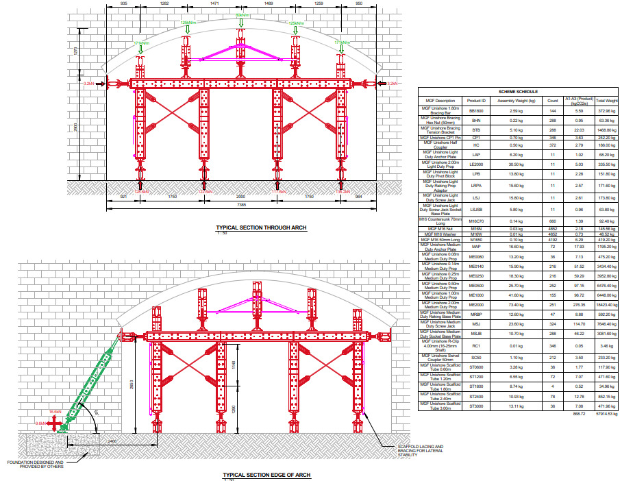
For Mount View Road, BDC developed temporary propping arrangements to support the underside of the arch during the relevant construction activities.
The proposed arrangement included multiple support beams running parallel to the arch ring, vertical props, raking props and associated bracing.
The design considered the skewed geometry of the bridge and the need to provide lateral stability on both sides of the temporary support arrangement.
The temporary works drawings incorporated:
-
Temporary beams and vertical support props beneath the arch.
-
Raking props providing lateral restraint.
-
Spreader arrangements to distribute applied loads.
-
Dedicated temporary foundations.
-
Support spacing coordinated with construction access requirements.
7.1 Temporary Foundation Design
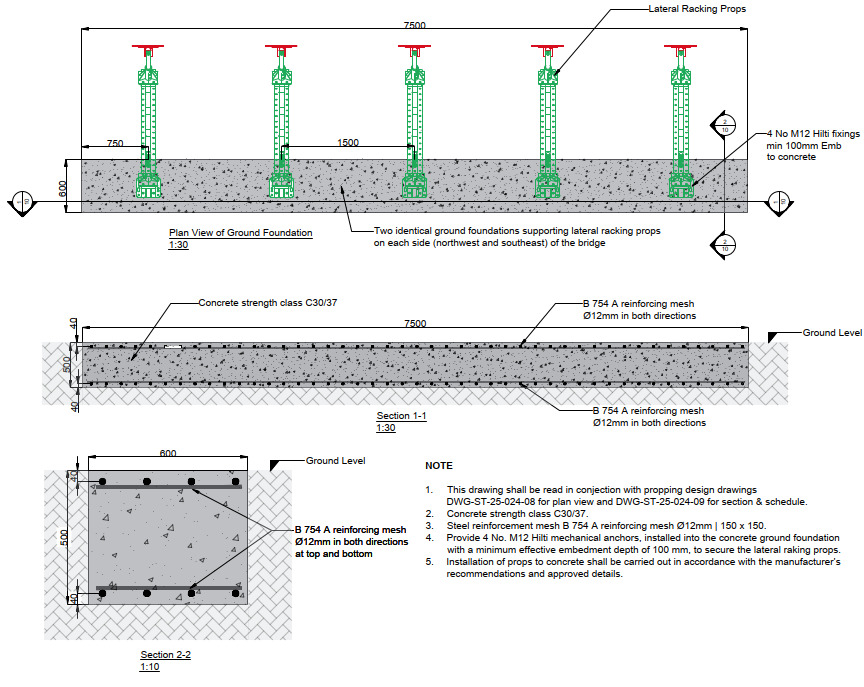
Dedicated reinforced concrete foundations were detailed to support the temporary propping arrangements at the northwest and southeast locations.
The foundation specification included:
-
C30/37 concrete.
-
B754A reinforcement mesh.
-
12 mm diameter reinforcement at 150 mm centres in both directions, top and bottom.
-
40 mm nominal concrete cover.
-
Four M12 Hilti mechanical anchors, with a minimum 100 mm embedment, for securing the lateral raking props.
These foundations were intended to provide suitable support and restraint for the temporary works arrangement, subject to the design assumptions and site verification.
7.2 Access Scaffolding
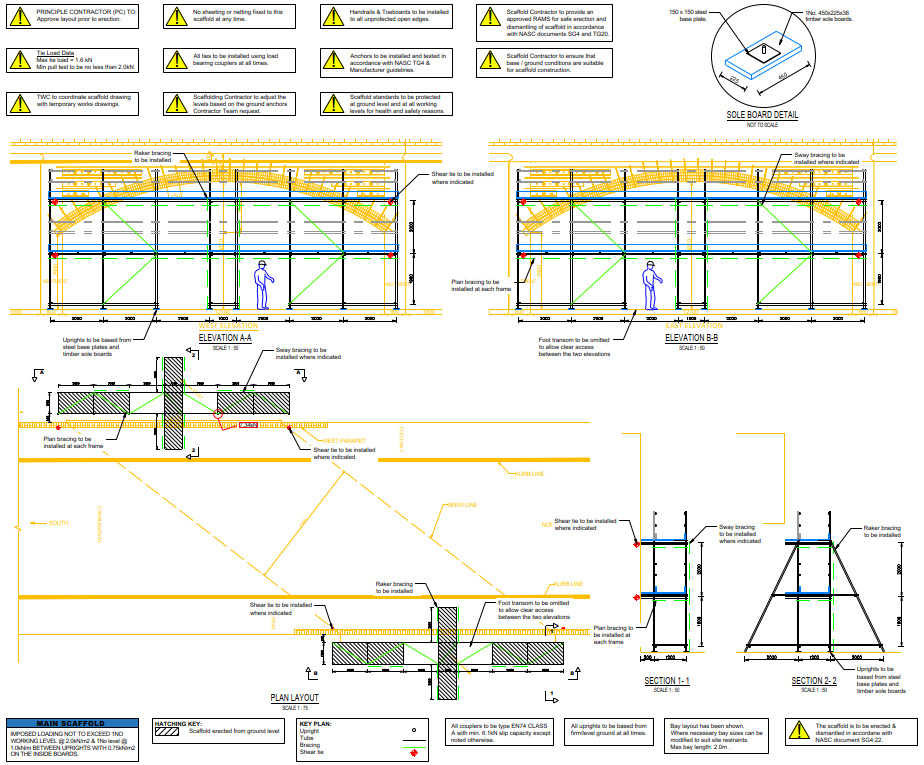
A dedicated access scaffold arrangement was developed to facilitate the strengthening and repair works to the bridge elevations and soffit.
The scaffold drawings specified a tube-and-coupler arrangement with a maximum bay spacing of 2.0 m, together with suitable sole boards and steel base plates.
The design also included working platform loading requirements, edge protection, scaffold ties and pull testing requirements.
Sheeting and netting were not permitted under the specified arrangement.
The scaffold layout was coordinated with the temporary works proposals to provide suitable access while minimising interference with the permanent strengthening operations.
The scaffold and temporary works arrangements were subject to coordination and approval by the relevant temporary works coordinator before construction.
7.3 Traffic Management and Construction Sequencing
The proposed strengthening works also required consideration of traffic management due to the bridge's location within an operational highway environment.
The design drawings identified different traffic management arrangements for ground anchor installation on the east and west elevations.
The proposed approach included:
-
Half-road closure on the east side during ground anchor installation to the east elevation.
-
Half-road closure on the west side during ground anchor installation to the west elevation.
-
No road closure anticipated for HeliBar installation to the elevations and soffit, subject to the proposed access and construction arrangements.
The temporary works drawings also considered alternative traffic arrangements to allow traffic to be maintained on one side while the opposite side was stabilised.
The final construction sequence and traffic management arrangements were to be confirmed by the contractor, taking account of the approved temporary works design, highway requirements and site-specific conditions.
8. Conclusion
The Mount View Road Bridge project demonstrates Beta Design Consultants' experience in the structural strengthening and remedial design of existing masonry arch infrastructure.
The approximately 38° skew bridge presented several engineering challenges associated with its existing masonry construction, spandrel wall restraint, buried utilities, restricted access and the need to maintain structural stability during construction.
BDC developed an integrated design package incorporating:
-
HeliBar crack stitching to the existing masonry.
-
Radial pins to the arch soffit.
-
Grouted GEWI® ground anchors and structural steel restraint members.
-
Localised masonry repairs and repointing.
-
Temporary propping and lateral restraint arrangements.
-
Dedicated reinforced concrete temporary foundations.
-
Access scaffolding and construction coordination details.
-
Trial hole investigation information and traffic management considerations.
By coordinating the permanent strengthening measures with the temporary works and construction requirements, BDC developed a comprehensive engineering solution addressing the structural defects and practical constraints associated with strengthening an existing masonry arch bridge.
The project highlights the importance of detailed condition information, appropriate strengthening techniques and carefully coordinated temporary works when working with existing masonry infrastructure.
Related projects
BP GF Gas Plant Asset Integrity and Refurbishment
Read More
Bus Depot Electrification Harrow
Read More
Concept Design of Cité Administrative Koloma
Read More
Structural Assessment of Henley Masonry Arch Bridge
Read More
Peckham Arch Condition Survey & Life Extension Consulting Services
Read More
Pembroke Road Footbridge - Structural Investigation & Strengthening
Read More
Concept Design of Sedhiou Bridge and Roads Network
Read More
Nant Melyn Bridge Inspection for Assessment
Read More
Clee Hill NATS Radar Tower
Read More
Hartlepool Solar Farm
Read More
Burrington NATS Radar Tower
Read More
Yeading Lane Bridge – Structural Assessment and CFRP Strengthening
Read More
Principal Inspection of 50 Highway Structures – Wakefield
Read More
Bus Depot Electrification – TfL Edgware Bus Depot
Read More
Action Court Warehouse Extension
Read More
CFRP and HPC Concrete Strengthening for Brindleyplace
Read More
Engine Yard Punching Shear Slab Strengthening
Read More
CPS House Jacketing to Strengthen RC Beams
Read More
BP Deep Water Sump Assessment and Concrete Repair Design
Read More
BP Heater Foundation Concrete Repair
Read More
BP GF Gas Plant – Slug Catcher Foundation Walls RC Repair
Read More
Fulham Palace Road Temporary Works Design
Read More
Harwell Campus-Concrete Strengthening
Read More
Kennedy Institute Extension - Flat Slab Punching Shear Strengthening
Read More
Structural Repairs of a Listed Building
Read More
Orchard House – RC Column Strengthening using CFRP
Read More
Stanmore House Strengthening
Read More
Energy from Waste Plant - Process Water Drainage Design
Read More
Northside Garages Structural Investigation
Read More
RAAC Investigation and Structural Strengthening
Read More
Spire Academy (Horizon Academy) Car Park Refurbishment
Read More
Planning Permission for 21 Boston Road Townhouse Conversion
Read More
Planning Application for Three Story Residential Building
Read More
Planning Permission for a Basement in a Conservation Area
Read More
London Hippodrome Roof Extension – Structural Design and Detailing
Read More
Structural Design of 3 Storey Building
Read More